|
Moog CP3 Mixer |
|
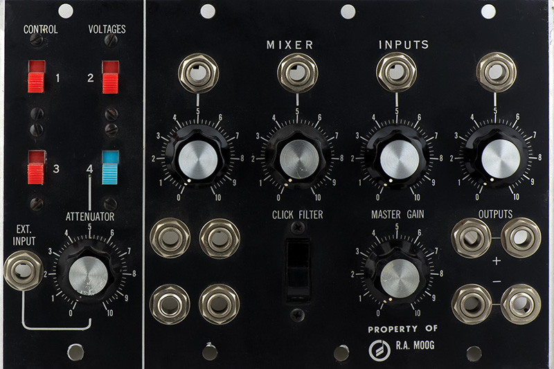
Console Panel 3 has switches for routing four controller CV signals, a four input mixer, a click filter, and four jacks that could be used as multiples or trunk routing. The switches are rear illuminated to indicate which controllers are patched in. The mixer provides non-inverted and inverted outputs with a master gain control. There are more photos and scope images on my Console Panel page.
This particular CP3 was not in a cabinet so I had a better opportunity to photograph it. I believe this particular CP3 was used as a service or test fixture at Moog. Note the "Property Of" legend on the panel.
There are two small PCBs on the panel. The lamp switches have been wired but no power wires have been ever connected to them. I took the opportunity to measure the current of the lamps. The lamps were originally wired on a 5V AC supply. Two diodes could be used to power the lamps from the -6V supply but it would use nearly 300 mA of supply current. The blue switch lamp takes considerably more current most likely because of the decreased opacity of the blue plastic.
| 6V DC | 4.8V DC | |
| Red switch lamp | 40 mA | 35 mA |
| Blue switch lamp | 170 mA | 150 mA |
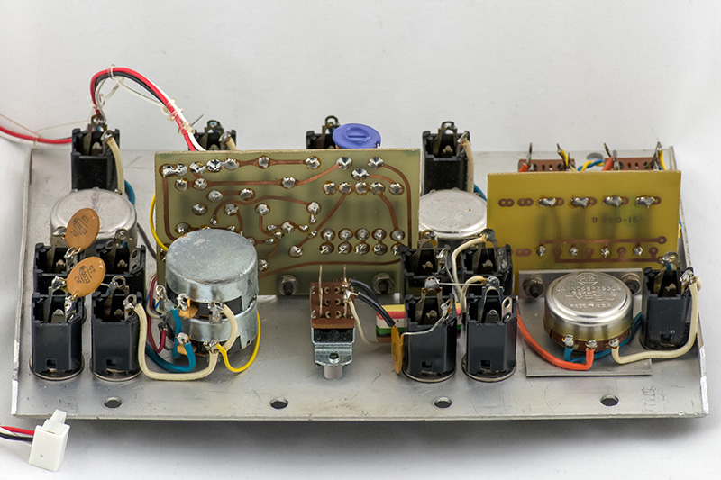
This image shows the top side of the PCBs.
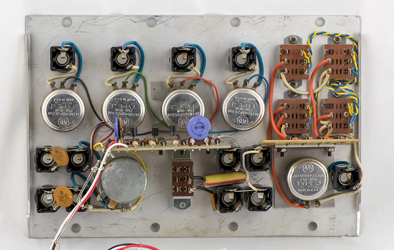
This image shows the bottom side of the PCBs.