|
230 Triple
Envelope |
|
I've only repaired these modules and do not have any photographs. I did however build a MEMS 230.
Modifications
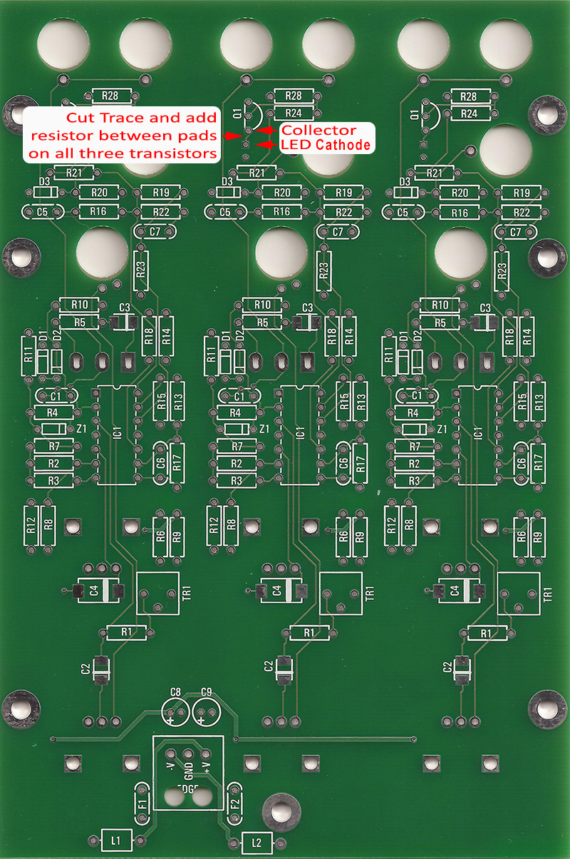
The original schematic has no current limit resistor in series with the drive transistor and will induce large current spikes which with result in audible clicks. This is either an error in the schematic or Don used LEDs with internal current limiting resistors.
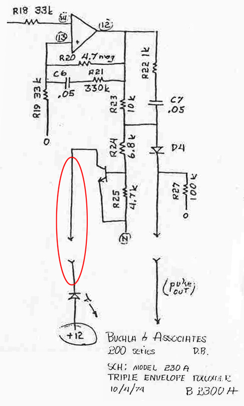
The fix is quite simple. Insert an appropriate current limit resistor between the collect and cathode. On V1 these two pins are connected with a trace on the rear of the PCB so it is easy to see and cut the trace and jumper the pads with a resistor. The resistor value depends upon the LED type and brightness desired. You can select resistors 1K and higher.
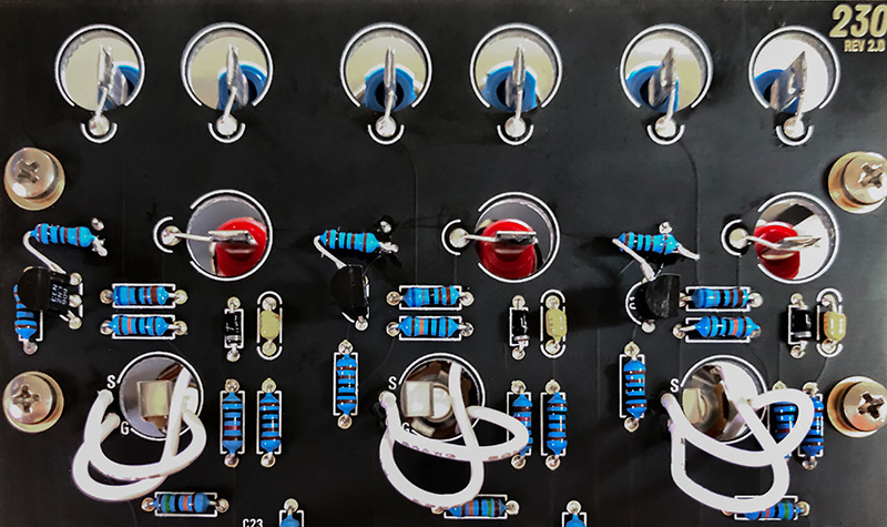
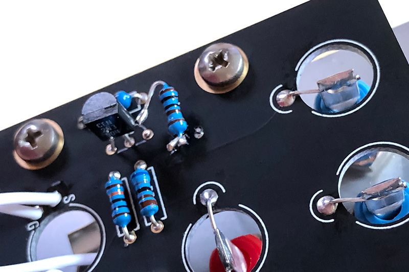
The V2 layout is a bit different. With the black solder mask it is difficult to see the traces. You can easily lift the collector of the transistor and solder the resistor from the lead to the pad. An individual sent me these photos of his modified V2 board.