|
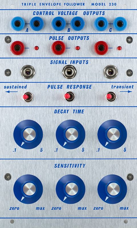
230M Triple
Envelope Follower |
|
The 230 consists of three independent envelope followers. Each has a sensitivity control and a decay time control.
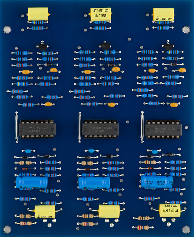
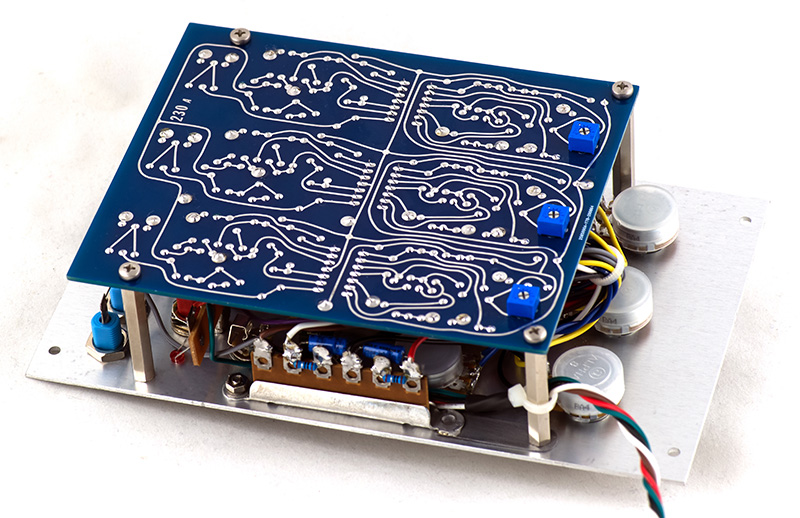
The PCB is quick to build. I mounted the trimmers on the rear to be able to calibrate the module when assembled. I chose non-polarized capacitors for the 1 µF and 4.7 µF capacitors.
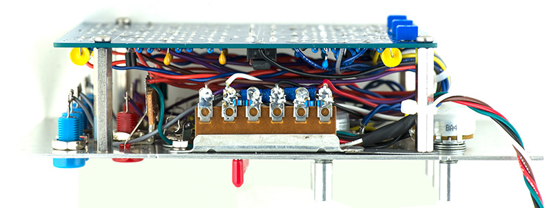
The front panel requires terminal strips for power supply decoupling and mounting the LEDs. The power supply terminal strip was shorter than the front panel mounting holes so I extended the lower end with a strip of steel to mount to the standoff. I made brackets for each of the pulse output jacks to mount a 3 terminal strip to mount the LEDs. I rotated the bottom row of potentiometers to simply add more clearance for mounting. This is most of the front panel wiring prior to installing the PCB.
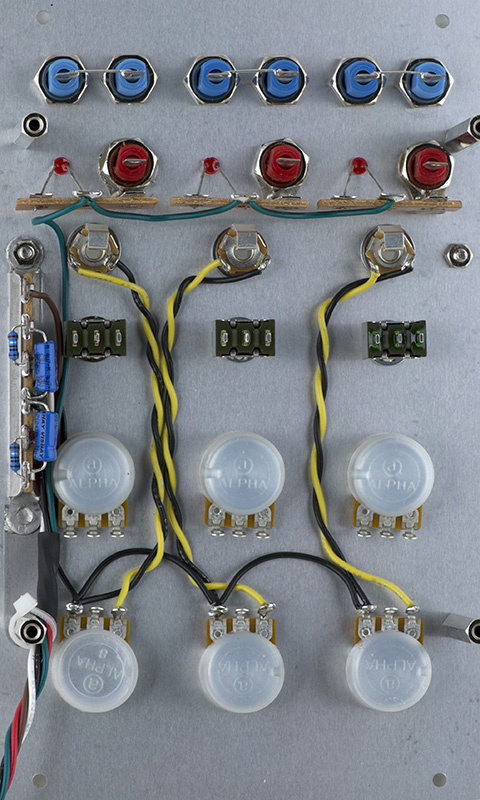
The panel-PCB wiring is quite tedious.

Calibration
The trimmers are adjusted to get close to 0V on the CV outputs. The sensitivity control does affect this so I adjust with no input but this control at maximum. When turned to minimum the CV will go slightly negative. This adjustment is very sensitive.
Operation
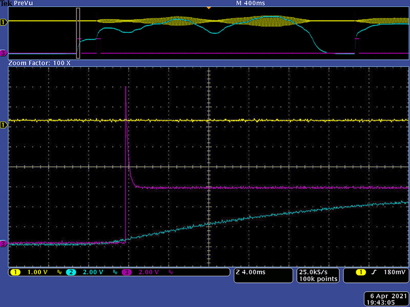
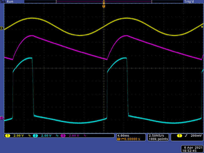
I had issues with some erratic behavior. The circuit design is a bit odd. I found oscillations at various places in the circuit. Shown here is the input signal, CV output, and the op-amp pin 1 output.
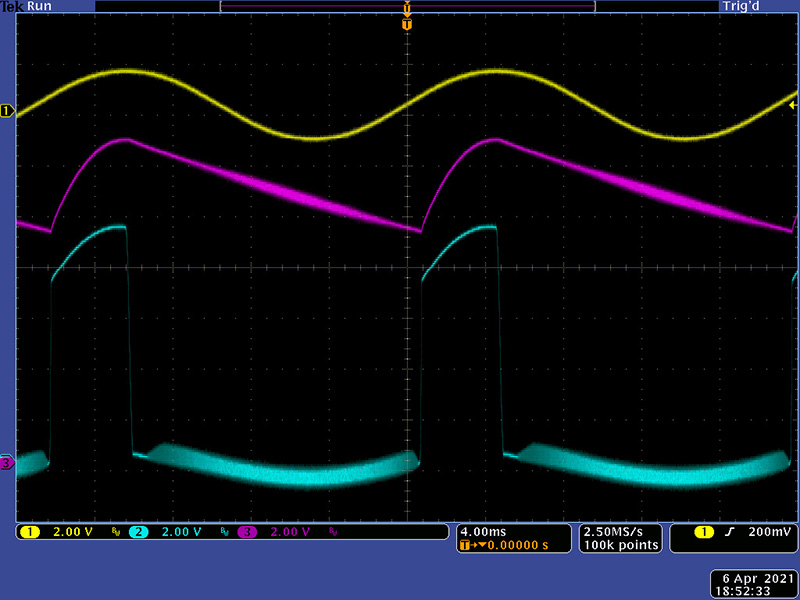
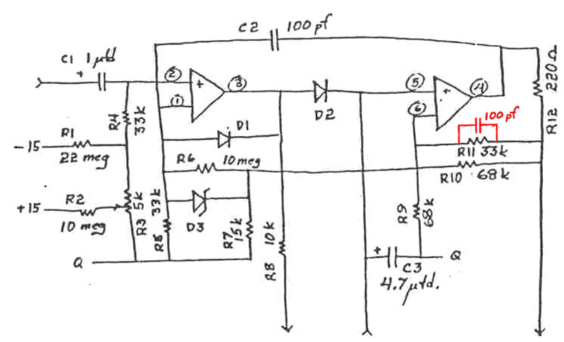
Adding a 100 pF capacitor across R11 tamed the oscillations.
This scope image shows the sustained pulse and the envelope with a higher value decay.
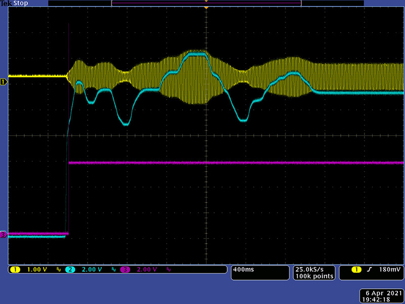
This scope image shows the transient pulse and the envelope with a higher value decay.
![]()
This scope image shows the transient pulse and the envelope with minimum decay. With minimum decay the CV is following the input frequency.
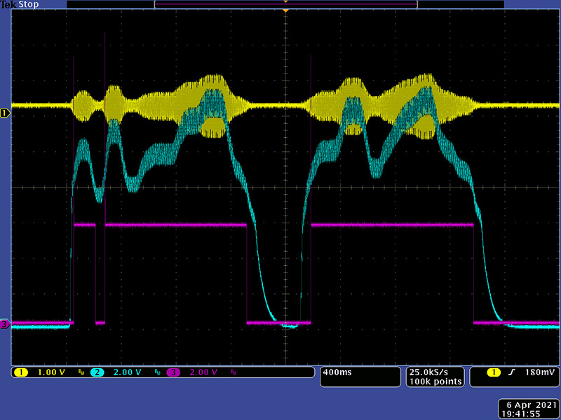
This image show the trigger and gate portions of the pulse output.