|
291M Dual
Voltage Controlled Filter |
|
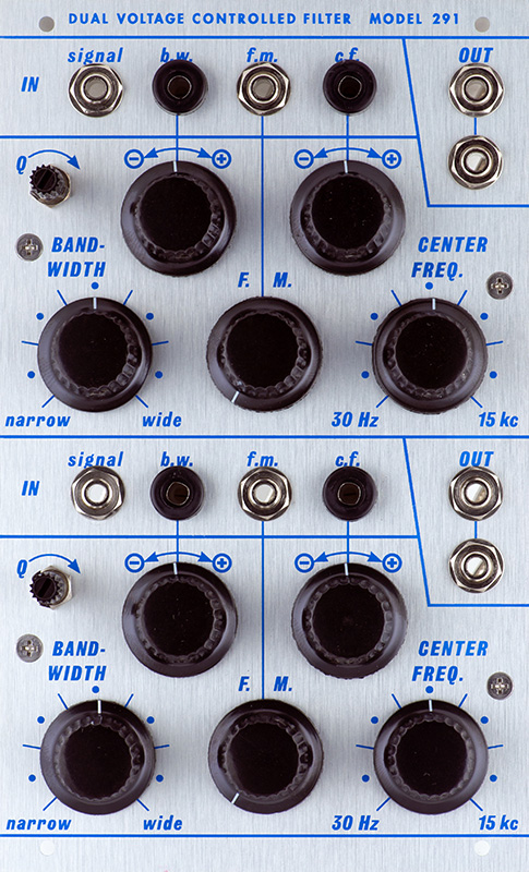
The 291 consists of two independent voltage controlled bandpass filters with adjustable bandwidth and center frequency. The center frequency is adjustable from 30 Hz to 15 kHz and the bandwidth is adjustable from one semitone to four octaves.
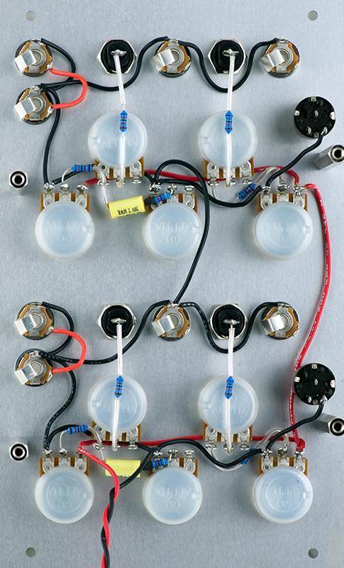
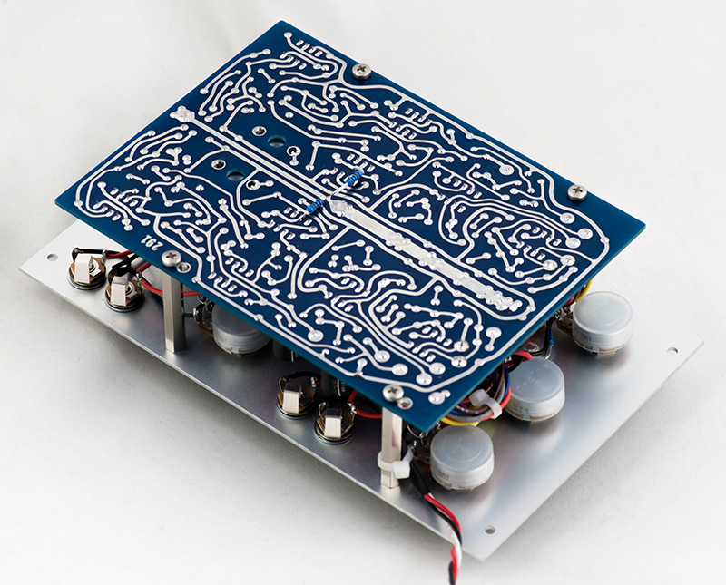
The rear panel wiring is nearly complete to mount the PCB.
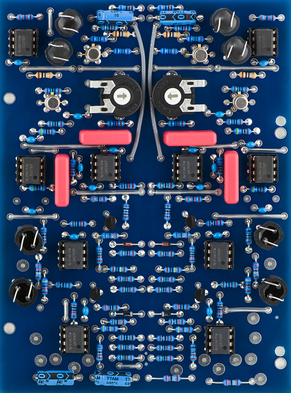
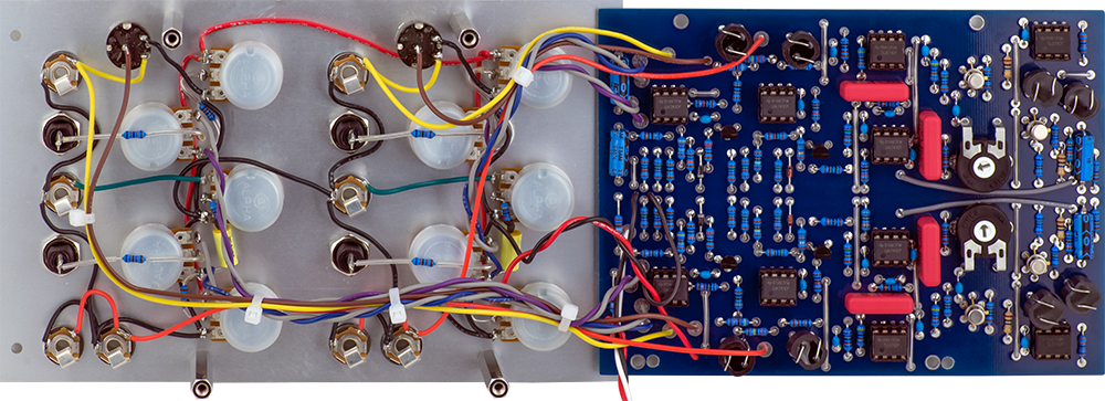
The PCB has a number of jumpers on it. I used Excelitis matched vactrols for VT2 and VT3 and Xvive matched vactrols for VT1 and VT4. The two extra mounting holes on the right are needed for the EMS panels which don't quite match the original design. There are also three smaller holes drilled for +15 and ground to the front panel and ground to the power cable. I did not initially install R48 and R49 which were added later to minimize high frequency oscillations. I had no high frequency oscillations but they didn't impact performance so I installed them. I did not select any of the dual JFETs for Idss.
Panel wiring is fairly straightforward as many of the connections are wired between panel components. I reversed violet and gray on the control so had reverse them on the PCB. The bottom filter is wired correctly but I still have to reverse the top filter.
Calibration
This is the first 291 that actually calibrated according the schematic. Set the Q and Bandwidth control to CCW and Center Frequency to mid. Apply a 2 KHz sine wave and adjust the trimmer so there is no self-oscillation.
Operation
This is an odd filter design that I don't fully understand. It seems to be a unique topology, possibly a twin-T filter but has some oddities. I suspect Don kept adding parts until he got the performance he wanted. As such its performance is what it is.
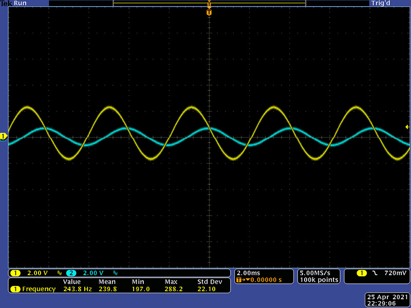
This is a 200 Hz sine wave with the Bandwidth near minimum and the Center Frequency adjusted for a peak output. Q has been adjusted for unity output.
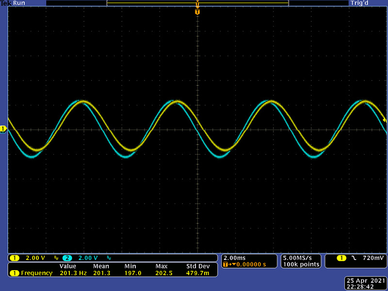
Decreasing the frequency 50 Hz results in an attenuation to 10%.
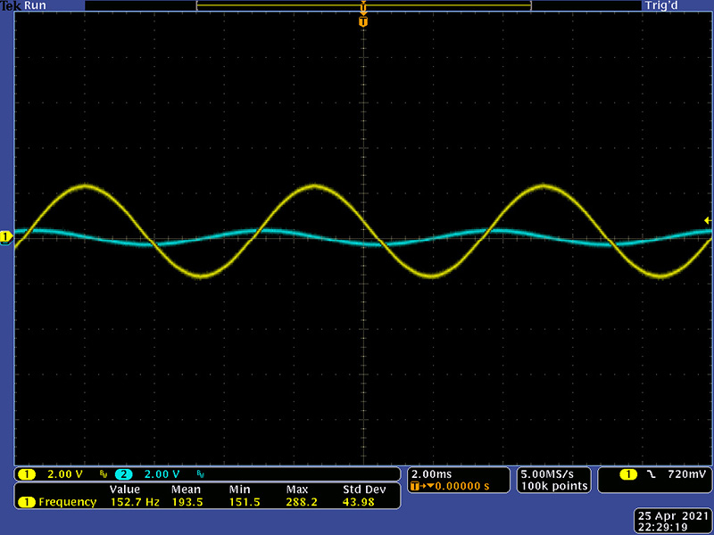
Increasing the frequency 50 Hz results in an attenuation to 17.5% demonstrating the bandpass nature of the filter.
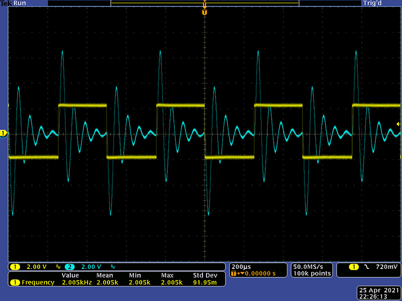
This is a 2 KHz square wave with some resonance showing the nice ringing. As you move the input frequency you can see "bounce" in the output resulting from the vactrol decay.