|
276M EEG Module |
|
From the MEMS website:
The EEG Conditioner was a one-off module that Don Buchla had designed for experimentation in biofeedback. Throughout the timeframe that Don was designing instruments, there was a general uptick in interest in studying Human Biofeedback as a therapeutic means. These experiments and the subsequent papers written about them had inspired a whole new generation of students and academic professionals to start looking inward.
More information can be found on the EEG Conditioner Model 276 on the MEMS website.
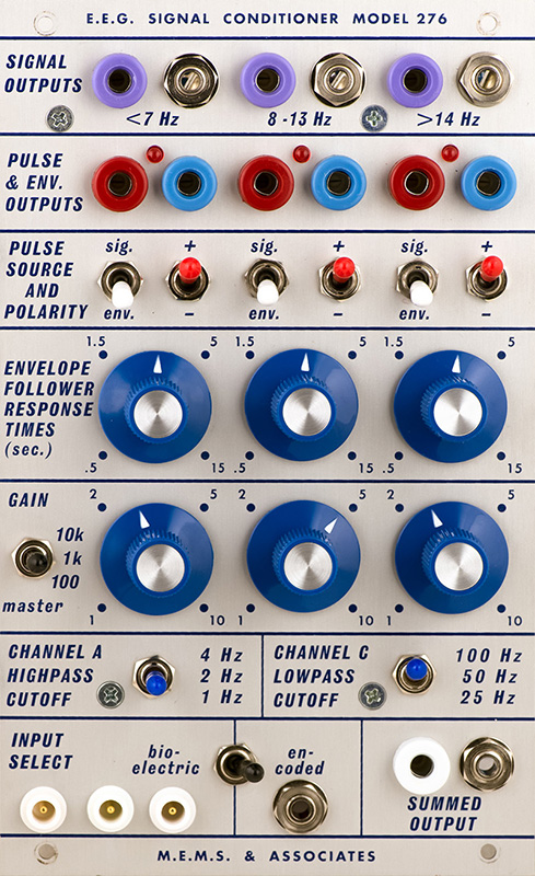
The module consists of a high gain (100x, 1,000x, 10,000x) instrumentation amplifier and a filter PCB. The instrumentation amplifier has 7 trimmers to accurately trim the offset voltage and common mode rejection.
The filter board consists of five 3-pole lowpass filters (100 Hz, 50 Hz, 25 Hz, 13 Hz, and 7 Hz) and five 3-pole highpass filters (14 Hz, 8 Hz, 4 Hz, 2 Hz, and 1 Hz). These filters are connected in series to provide switch-selectable bandpass filters. Channel A (left side) is selectable between 1-7 Hz, 2-7 Hz, and 4-7 Hz (Theta). Channel B (center) is fixed at 8-13 Hz (Alpha). Channel C (right) is selectable between 14-100 Hz, 14-50 Hz , and 14-25 Hz (Beta). Each channel has an input attenuator control.
Each of these three channels has a high level bipolar CV output and an attenuated signal level audio output. Each channel feeds an envelope follower with a variable response time. The outputs are CV and a pulse. The pulse is selectable on the signal input or envelope output. A polarity switch defines the type of pulse output. Env and + is a traditional trigger/gate. Env and - is an end- of- gate pulse. Signal and + is a RC pulse on the negative crossing of the audio signal. Signal and - is a rectangular pulse on the positive crossing of the audio signal.
The input is selectable between the internal instrumentation amplifier or an external signal input. The summed output 1s not wired on this prototype and would be the sum of channels A, B, and C for a 1 - 100 Hz output.
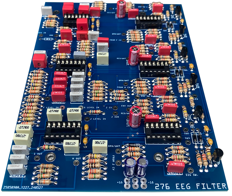
Construction
The filter board contains the ten filters and three envelope followers. I did not take a full-on front view photo.
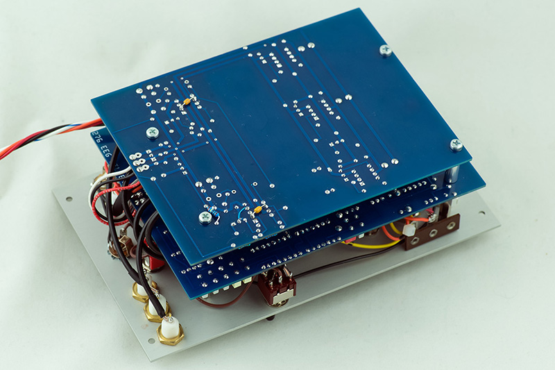
There is a fair amount of wiring to the panel.

The instrumentation amplifier board simply has power, a differential input, and three outputs. The module requires +/15V and 5V.
Calibration
The only calibration required is on the instrumentation amplifier. The differential input gain amplifiers interact so you have to ground the interconnection between the two 51R resistors. You can then trim the offset to <1mV. The differential op-amp is AC coupled so ground the inputs and trim the offset to <1mV. The two follow-on 10x gain op-amps can then be trimmed to <1 mV. The three inputs on the front (L to R) are +, -, Gnd. Connect + to - to a stable DC supply. I chose 1.5V. Adjust the Zero trimmer so the differential voltage between the two input gain amplifiers is 0V. Then short the two capacitors to provide DC coupling and adjust the CMRR trimmer for 0V on the 100x output.
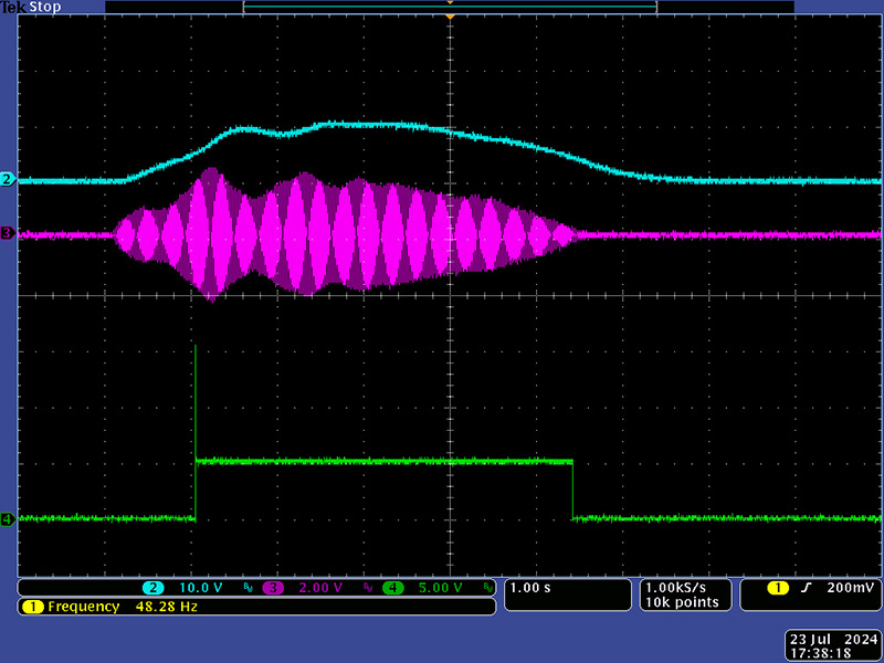
Operation
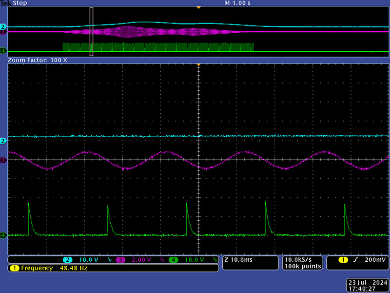
This scope photo shows the envelope follower and the resulting trigger-gate pulse (Env and +).
This scope photo shows the amplitude and pulse width of the trigger.

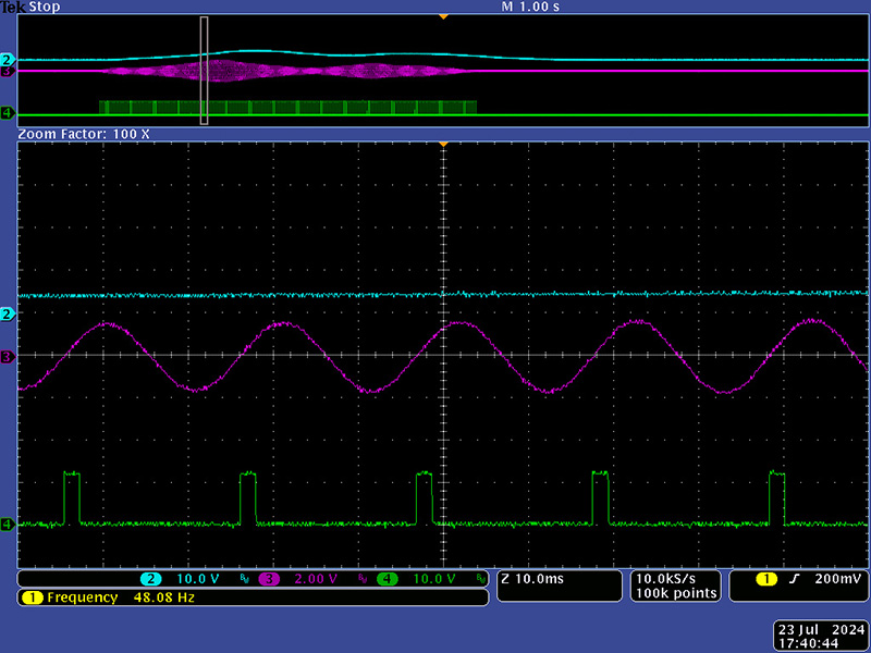
This scope photo shows the end of gate pulse (Env and -).

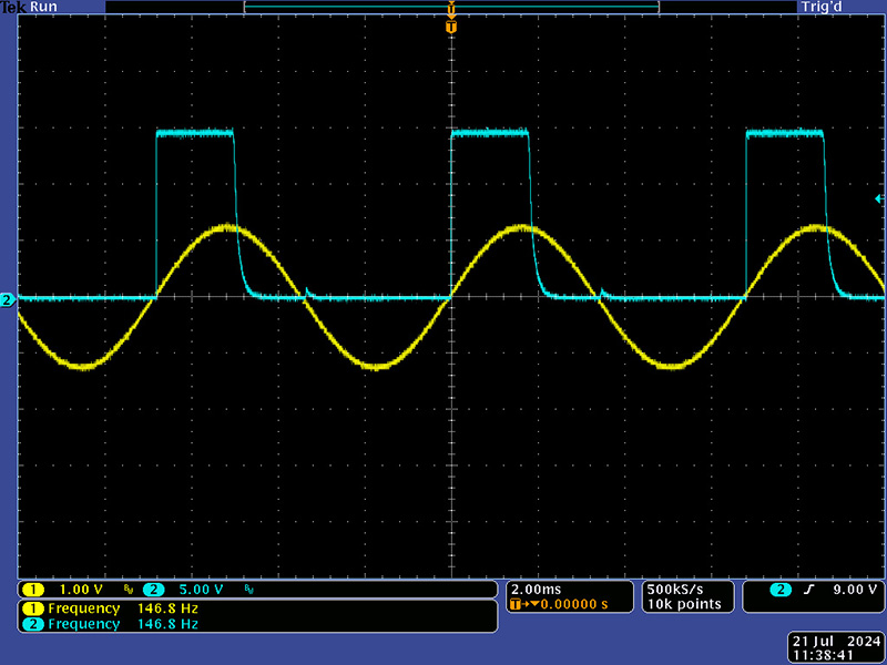
This scope photo shows the signal and RC pulse (Sig and +).
This scope photo shows the detail of the RC pulse. With the + used for the trigger-gate, it unfortunately is used here with the negative signal crossing.

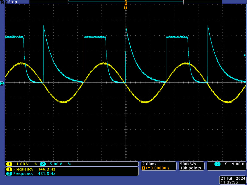
This scope photo shows the signal and RC pulse (Sig and -)
This scope photo shows the detail of the rectangular pulse.
The prototype was built with SPDT polarity switches. The schematics call out On-On-On switches not wired as 3 way. The center position would be the sum (logical OR) of both signals as shown in these next two scope photos.

I did not have any time to try actual operation with brain waves as I needed to return the module to MEMS to be able to attend Electric Eclectics festival. Electric Eclectics is a festival of avant-garde and crossover musicians, as well as art installations, DJs, and films held on a farm overlooking the scenic Big Head Valley, just outside of Meaford, Ontario.
MEMS demonstrated the 276 EEG Conditioner in their "EEGeasel" module and had a sign-up for people to give the 276 a tryout. This photo of their EEGeasel is courtesy of MEMs. More information can be found on the Modwiggler topic Exploring the 276 EEG Conditioner at Electric Eclectics.