|
275M Dual
Equalizer / Reverb |
|
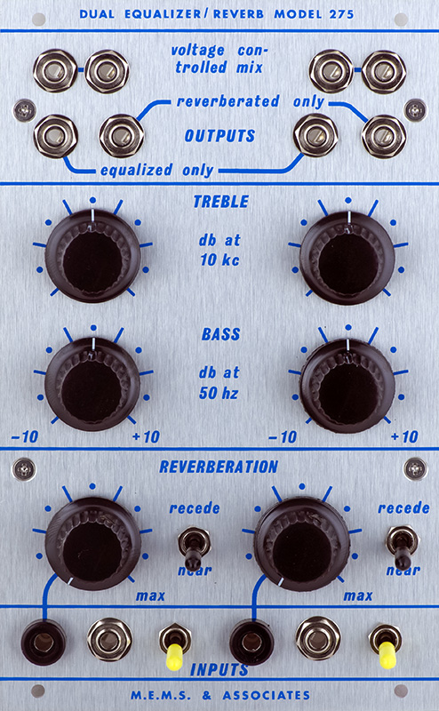
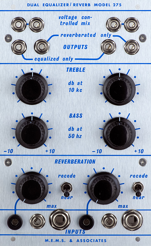
The 275 is a dual equalizer and reverb. It consists of two separate physical units. The module is simply a voltage controlled dry / wet mix with a mode to switch between near and recede. The rear of the module consists of the reverb send and return jacks for both channels. The second unit is simply a stereo reverb unit with signal in and reverb out jacks and is mounted at the rear of the cabinet.
Module
The panel module consists of two identical channels. There is a single signal input which feeds three sections: the monitor output enabled by a switch, a bass / treble equalizer, and the output signal to the reverb unit. There is a single control and CV input which controls the mix of the dry and wet signals.
There are multiple panel output jacks consisting of the equalized signal only, the wet-only reverb signal, and the dry/wet mix. External to the panel are two additional outputs consisting of the monitor output and a surround output.
The two modes are near and recede.
In near, the mix output cross fades dry to wet over the CV range. This has the effect of the sound being near and then moving farther. Surround has no output.
In recede, the dry signal portion of the mix output is muted for the first quarter and then increases over the final three quarters of the CV range. The wet signal portion of the mix output increases for the first third, decreases for the next third, and is muted for the final third of the CV range. This has the effect of the sound being far and then moving nearer. The surround output consists only of the wet signal which is muted for the first third, increases for the next third, and decreases for the final third of the CV range. This would interconnect via the rear of the module to the 204 Spatial Director to add equally to all four channel outputs. As sound is panned around the quadrant, it has the effect of reverb in the other three corners thus surrounding the listener.
Since the module has just standard send and return signals it can be used with any external effects unit as long as it can handle 4V pk-pk signal levels.
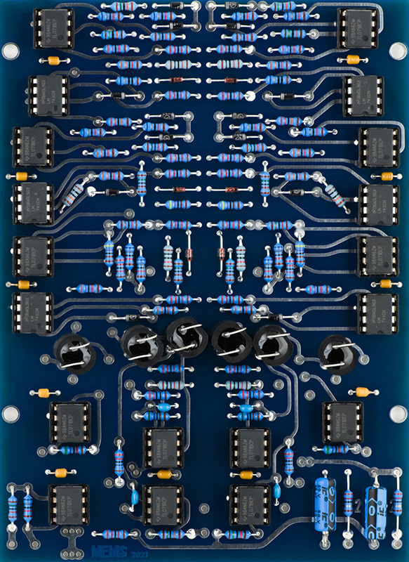
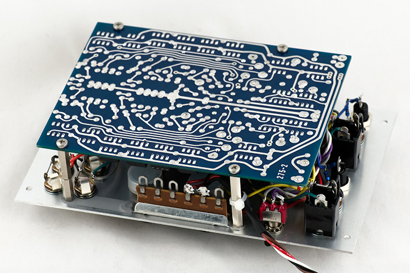
The CV input is setup for a 0 to 15V range. This photo is before testing and modifications.
Reverb Unit
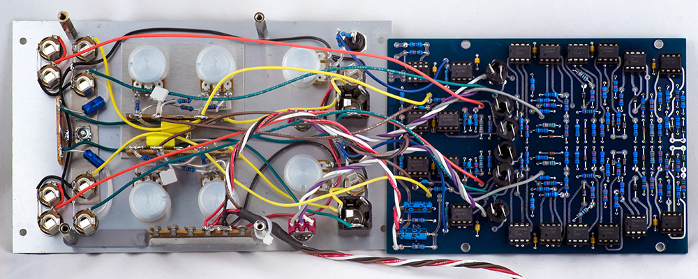
The reverb unit consists of two channels of reverb with 200 series signal level inputs and outputs, requires +/-24V and +/-15V, and is physically large. What is unique is that it also contains a noise gate so that when there is no input signal, the output is muted to minimize ambient reverb noise.
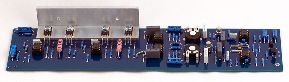
I have machined the heat sink for the reverb drivers which mounts on the PCB. The PCB mounts by the heat sink and one PCB mounting hole in the lower right corner.
Construction
There is a lot of front panel wiring. I made two aluminum brackets to hold three terminal strips to mount components to. I soldered a steel strip to the in-line terminal strip for power and notched it to fit around the jack.
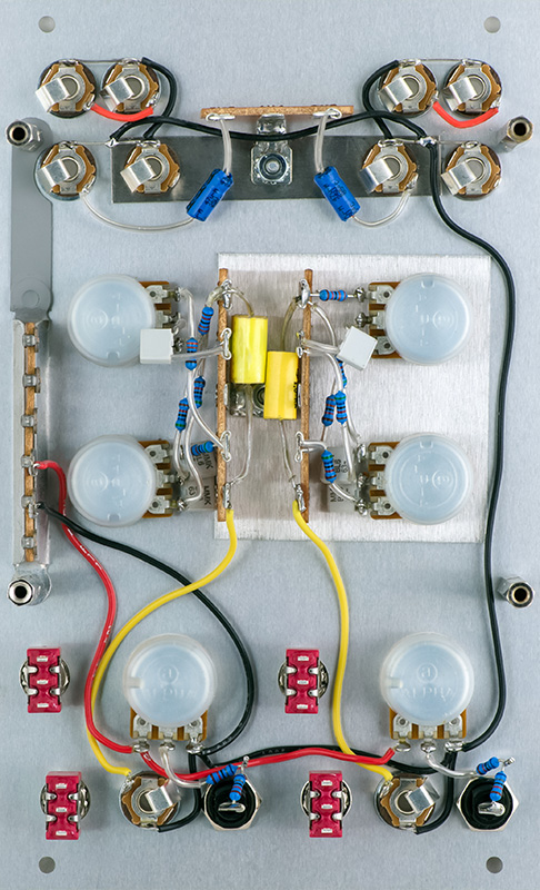
I did not wire up the monitor switch which would connect to the input jack and have a 68K resistor in-line. I do not utilize the monitoring signals in my setup so I chose to replace this switch with a 1/4" TRS jack for a generic send/return from the front panel. That allows me the flexibility of using the spring reverb unit or any external effects unit. I ground the switch holes upwards so the jack would not sit closer to the rails.
There is more wiring but a bit easier since there are now terminals for the send and return signals. The bottom 68K resistor from the banana jack changes to 45K3 for a 0 to 10V CV range.
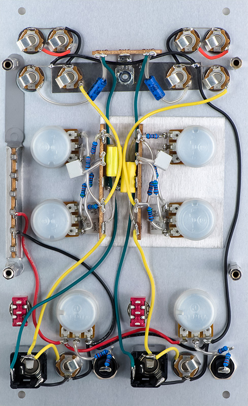
Panel wiring is complete. I did not wire the -15V and N to the terminal strip since they only go to the PCB.
You can see in this photo how my 1/4" TRS jacks are flush with the other jacks across the bottom to allow for lip clearance.
Module Operation
I tested the module first. I patched a setup with a 0 to 15V CV from my 284. I chose 10 seconds to minimize vactrol response time. The surround output is designed for a 204 with a 33K input resistor so I terminated this output with 33K.
I patched an 800 Hz sine wave into the input and a 2 KHz sine wave into the return. I took the mix output to my 296 to separate the output back into these two frequency bands. That way I can monitor the "dry" signal at the 800 Hz output and the "wet" at the 2 KHz output.
Tone controls are set to flat.
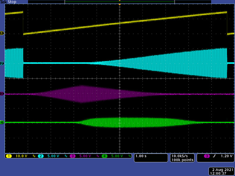
Here are the three outputs in Near mode (cyan=dry, magenta=wet, green=surround).
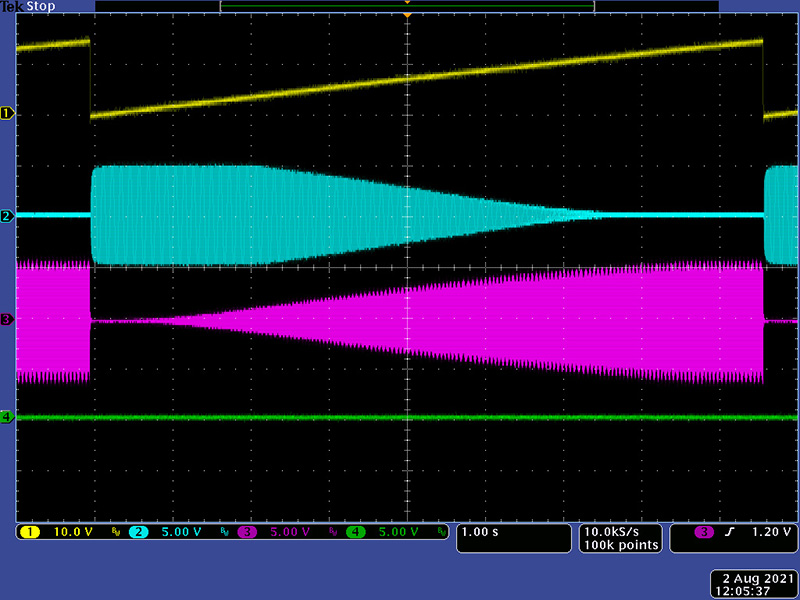
Here are the three outputs in Recede mode (cyan=dry, magenta=wet, green=surround).
For the Bass and Treble controls I setup a sweep from 25 Hz to 5 KHz (I didn't take the time to verify the upper sweep frequency). Here both Bass and Treble are set to flat (cyan=input, magenta=equalized output).
Bass set to full boost with Treble flat.
Bass set to full cut with Treble flat.
Treble set to full boost with Bass flat (note only to 5 KHz).
Treble set to full cut with Bass flat (note only to 5 KHz).
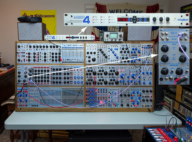
It probably violates some unwritten Buchla tenant but here is my 275 with a late 1980s Digitech MSP4 as the external effects unit.
Reverb Module
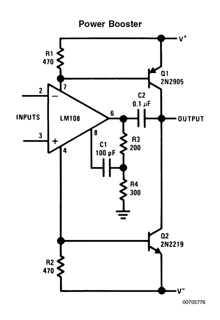
The reverb driver is an interesting configuration, and one that was typical in the 1970s. +/-24V is used for the driver output stage consisting of complementary symmetry transistors driven from a MC1456 op-amp. The base of the output transistors are driven from the op-amp power supply pins which was a common practice in the 1970s. Here's an example of this topology from the National Semiconductor Application Note 31 Op Amp Circuit Collection. Zener diodes have been added to to the supply pins to drop the supply voltage down to 30 volts for the MC1496.
I used some spare Fender reverb tanks which are 8R input and 2250R output using long springs. A 100R series resistor in the output creates a "poor man's" current source drive to compensate for the increasing tank impedance with frequency.
I first powered up the system using a bench supply for the +/-24V and my linear supply for the +/-15V and had significant high frequency oscillations. I added 0.01 decoupling capacitors which were used in the external system to the PCB, increased power wiring size, and used a single supply by tapping off the unregulated voltage on my linear supply. This provided about +/-23V albeit with about 100 mV of ripple. I used shielded cable to the reverb tank and grounded the case. This eliminated my high frequency oscillations and made the system more stable although the ripple was somewhat noticeable on the output. It would be good to evaluate performance with a with a good four output power supply.
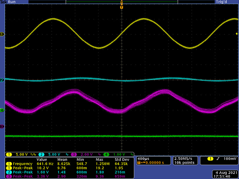
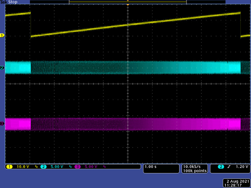
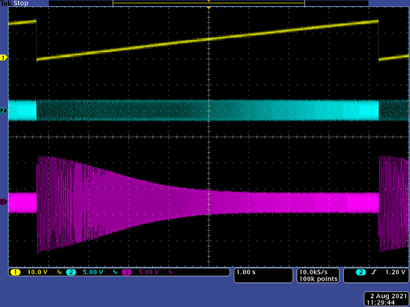
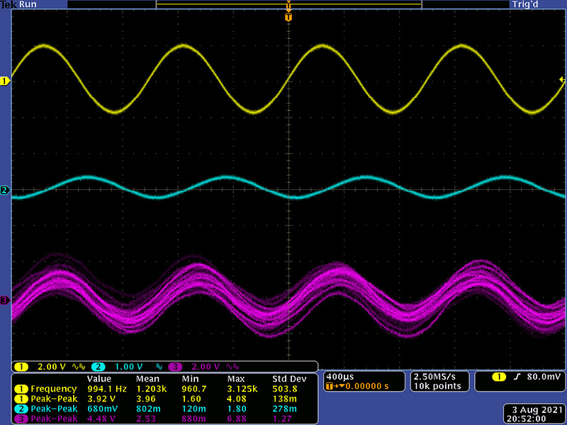
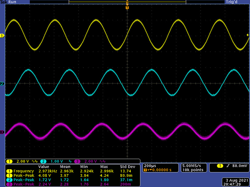
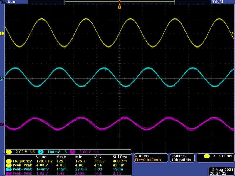
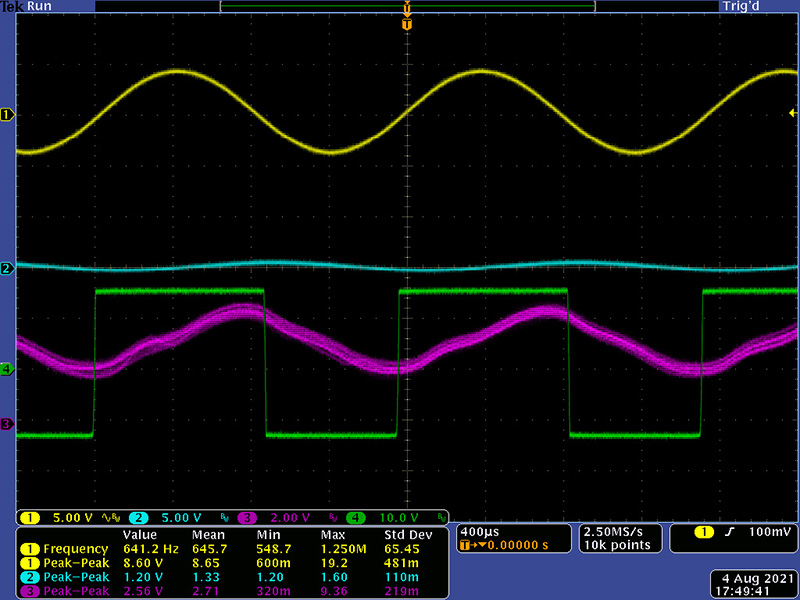
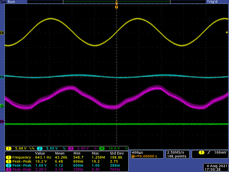
These scope images consist of the 4V pk-pk input signal (yellow), reverb tank drive after the series resistor (cyan), and the signal output after the recovery amplifier (magenta). These images are with a TL071 used in both the driver and recovery circuits. Channel 3, the output, is set to AC coupled. This signal has about a 3VDC offset so needs capacitive coupling which the module provides.
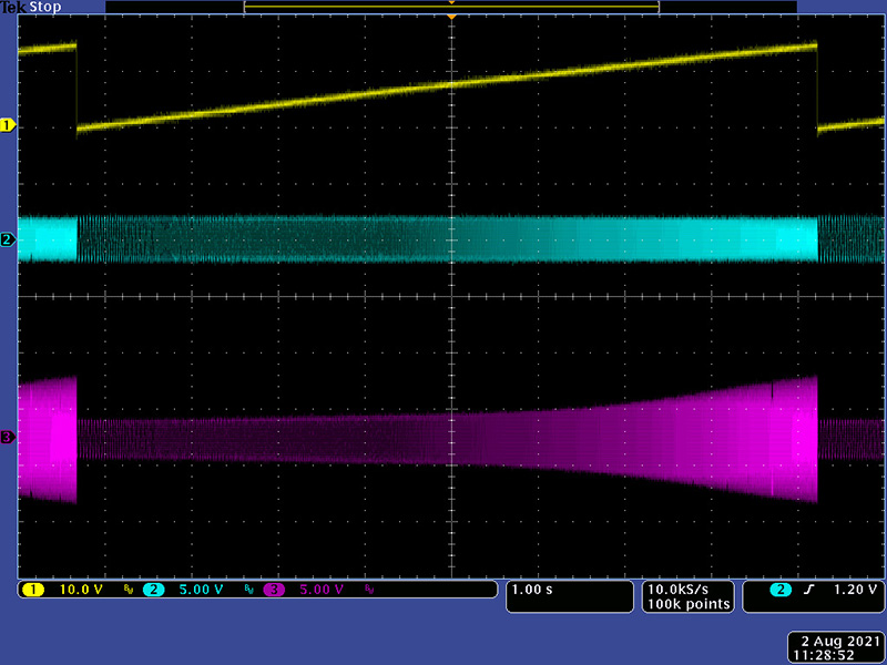
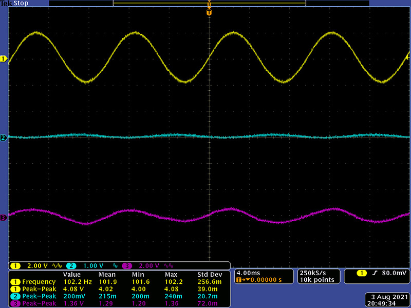
At 100 Hz there is still good performance with the output level just starting to drop off. The output level drop significantly by 50 Hz. You can see how low the reverb tank drive signal is since the tank input impedance is low and the series resistor becomes significant.
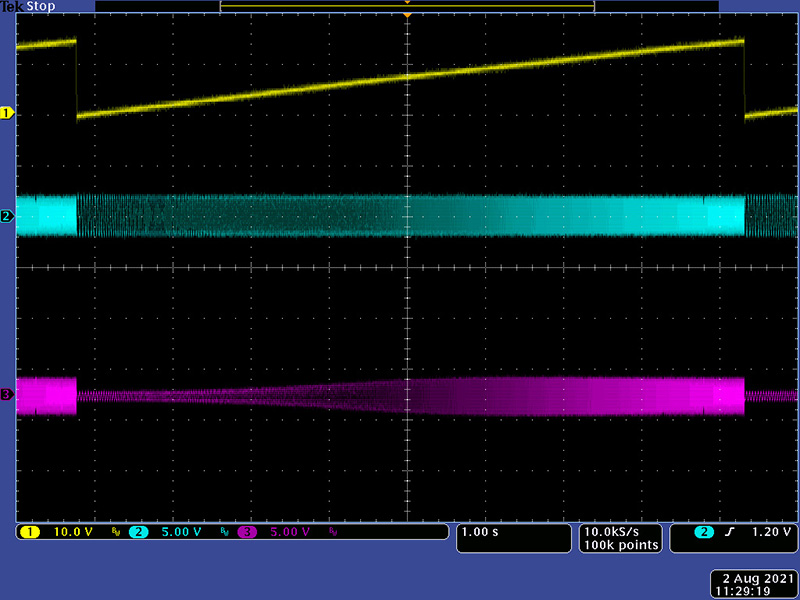
At 3 KHz there is still good performance but the output level drops significantly by 3.5 KHz. You can see how high the reverb tank drive signal is since the tank input impedance is high and the series resistor becomes negligible.
At 1 KHz the output is just under 2V pk-pk output. There are natural resonances in the tank so the output level varies with frequency. One could boost the gain of the recovery amplifier for a bit hotter output.

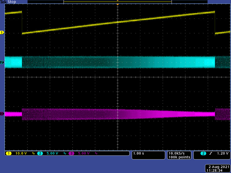
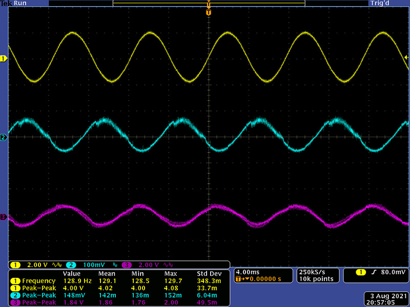
I changed to the original MC1456 for the recovery op-amp which made little difference. When changing to the MC1456 for the driver op-amp there was more distortion in the signal. This tank drive signal (cyan) using a TL071 is reasonably clean.
You can see the distortion increase when using a MC1456. I do not know if the ripple in the +/-24V supply has any impact on this. I replaced all the MC1456 op-amps with TL071.
Modifications
The reverb drive signal is fairly low level with a 4V pk-pk input. The reason for the +/-24 was likely more for current requirements and isolation. There are 5 zener diodes to drop the voltage for IC1 and IC2. I replaced these with links and operated the reverb module from +/-15V only. At a 13.2V input the output was 28.6V pk-pk without clipping.
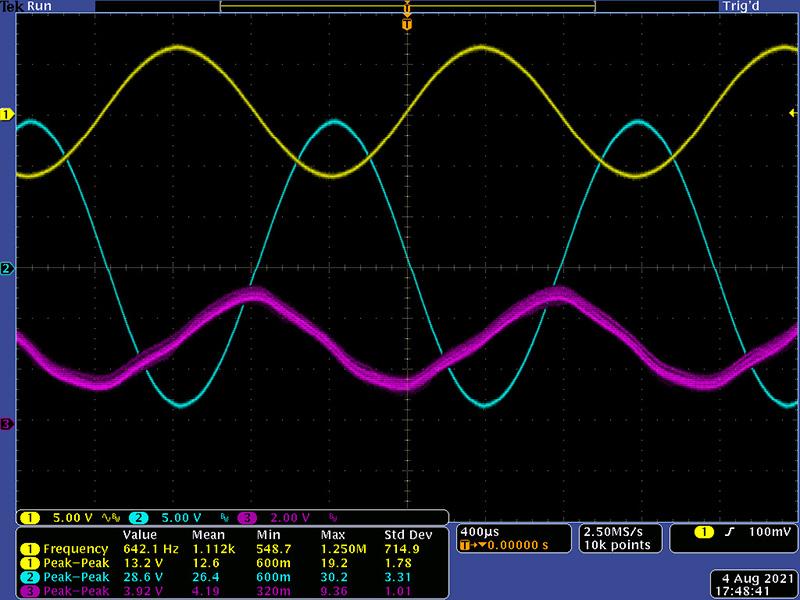
I over- drove the input to watch for clipping which occurs soon after 13.2V. At 14.6V there is significant clipping at the power supply rails. The reverb output level increases with input signal to a point and then stops so there is no need to drive the tank this hard. There is plenty of headroom to operate this module on +/-15V only. Driven to maximum unclipped output on one channel only had a draw of approximately 50 mA on both supplies.

I do not plan to mount this in a steel enclosure with two reverb tanks as I am fine with my external effects unit. I have plenty of +/-15V capacity so I would investigate further operating it on those supplies only. I left the input signal pretty high and looked at the noise gate circuitry. The green is the output of IC2 which is operating as a comparator.
That output is rectified and filtered forming a negative peak detect level. Here it is operating about -12V.
The trimmer adjust the negative peak detect level to operate the JFET noise gate. I adjusted it so that at a low input signal level the output would mute. With this high of a level it is operating at -1.7V.