|
259M Complex
Waveform Generator |
|
The 259 Complex Waveform Generator uses a panel PCB to mount the switches and controls greatly simplifying construction. PCB1 is designed for CTS potentiometers for all but the two upper right controls which are the 1/8" shaft PRV6 style which require adapters for 1/4" knobs.
I decreased the scale trimmers from 100K to 20K to decrease their sensitivity.
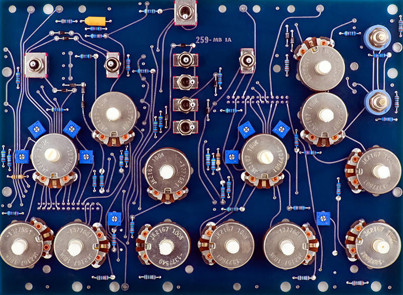
I epoxied the tempcos to their respective exponential pairs.
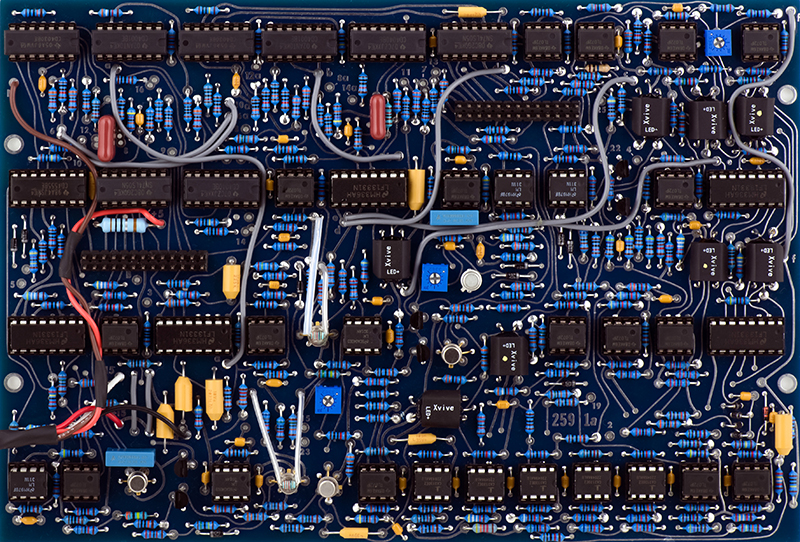
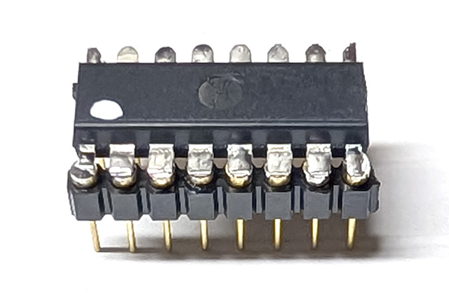
This module uses five LF13331 CMOS switches. These are rare, difficult to find, and those that you can find may or may not be fakes. The DG442 has the exact equivalent function but with superior performance: lower Ron, wider signal range, and lower crosstalk. Iit does not have a disable pin which is not used in the 259. However, four pins are swapped which makes it not a drop-in replacement. MEMS makes a LF13331 replacer using a SMT version of the DG442 which works in all five locations.
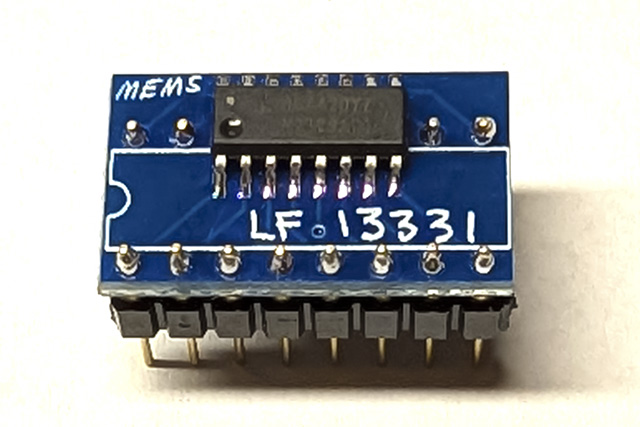
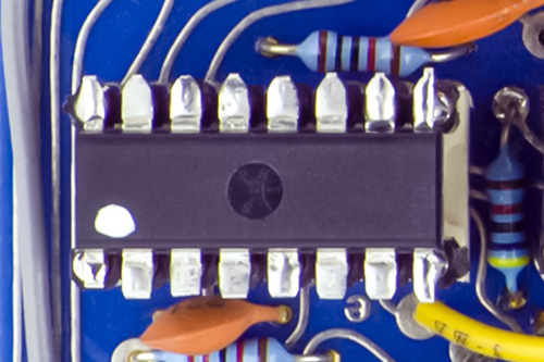
This image shows it replacing IC24 on the PCB.
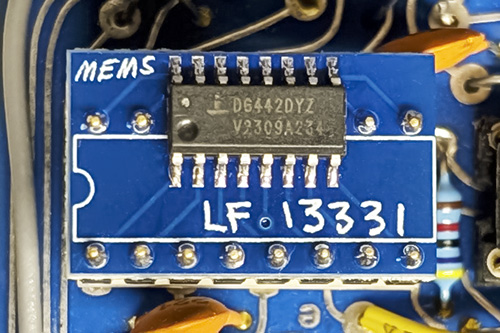
Interestingly enough, if you mount a DIP DG442 upside down and rotated 180 degrees, all the pins all line up for a direct replacement. I've marked the new pin 1 with a white dot.
This shows it also replacing IC24.
Modifications
Almost all of the off-PCB pads have pull-up or pull-down resistors to terminate input signals. The exception are the four inputs for the MO and PO LEDs. IC8 and IC13 are used as buffers and inverters driven by a common signal to generate alternate blinking LEDs. These inputs are floating and the LEDs might blink together, alternately, stay on, stay off or flicker. Since I will never drive these inputs with external signals, I wired them to the 5V supply pins of IC8 and 13. Connect pads 6 and 10a to ground and pads 10 and 6a to +5V. When the square wave output is positive the top LED will be ON and when negative, the bottom LED will be ON.
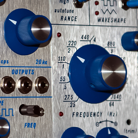
I've always disliked the frequency knobs on the 259. I don't like the puck style at all and I find them hard to adjust with the large diameter. I don't like the proportions of the large blue skirted knob as they seem too tall. I decided to shorten my knobs on my lathe. The location of the set screws limits the amount they can be shortened by about 0.175" which looks good to me. The potentiometer shafts are long enough to fit either knob.
Jim Fowler posted this photo on Modwiggler showing two different knob heights.
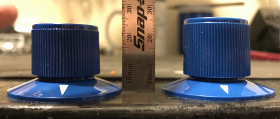
A follow-on post detailed the specs for two different 1.5" diameter knobs.
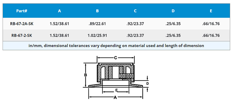
I bought these knobs from Amplified Parts and they must have been the RB-67-2-SK. I went and measured my modified knob heights and amazingly they are 22.5 mm high, so correspond very close to the RB-67-2A-SK knobs. Live and learn.
Operation
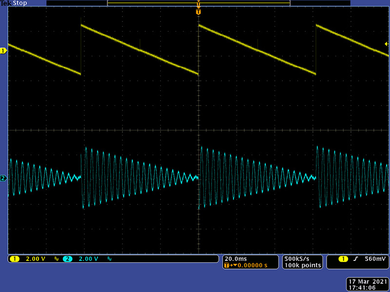
These images show the MO modulating the CO. First is AM modulation.
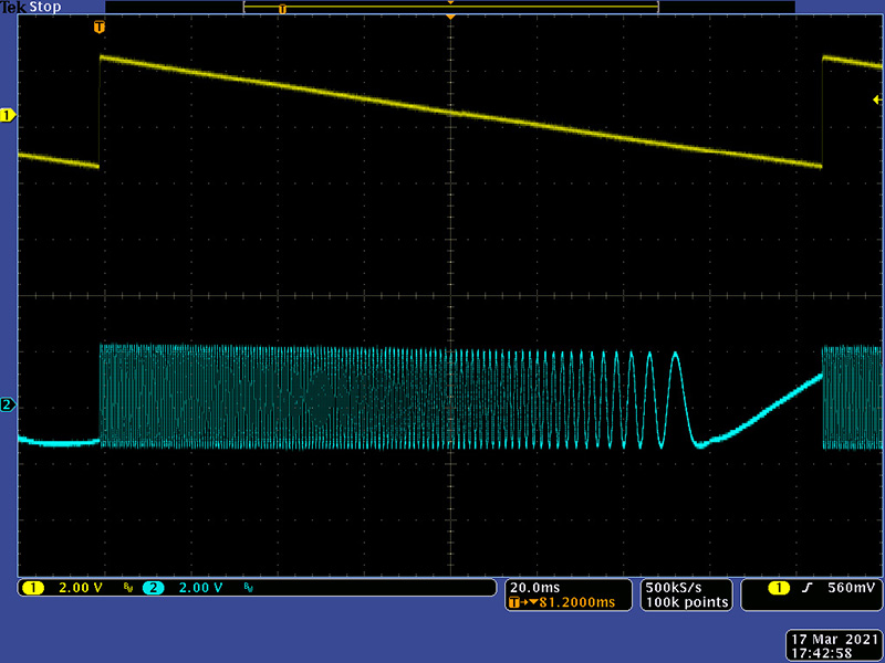
FM modulation.
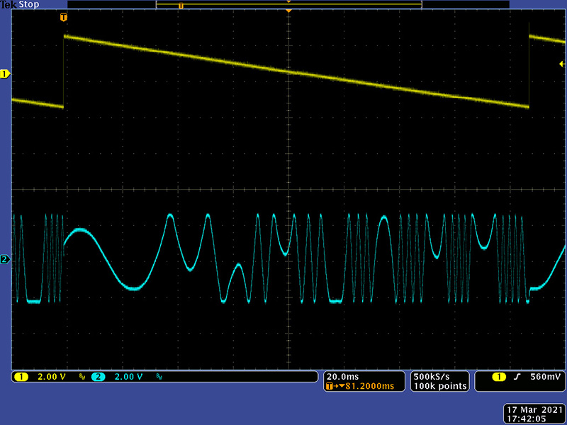
And finally timbre modulation.
I made the modifications to add hysteresis to the CO square wave comparator to eliminate oscillations on the rising edge. This image shows the square, sine, and final output with timbre.
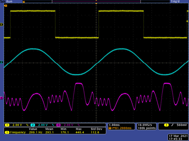
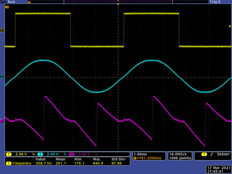
Increasing the order produces a this saw waveform.
Increasing symmetry produces this wavefolded sine waveform.

Calibration
Calibration is the same as the 259r and is documented on that page about 1/3 down.
259r Page with Calibration Instructions