|
223M Location
Voltage Processor |
|
The 223 Location Voltage Processor is intended to be used with the 227 System Interface Module in a quad setup. It contains four separate voltage controlled processors that output an X and a Y voltage for the 227 assign inputs.
The top row of knobs defines the operating range by adjusting the baseline of operation. The Balance adjusts the left to right panning. The Cross-Pan controls row modifies both the X and Y outputs and the exact function changes with the setting of the Balance control. These controls are described in more detail under Operations below.

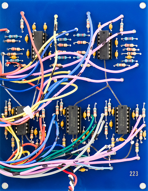
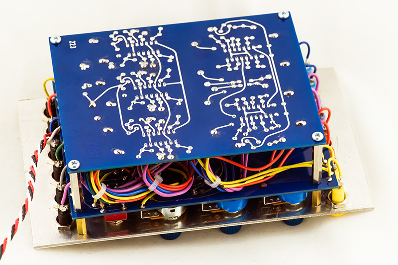
Construction
The original 223 was hand wired on a prototype board. MEMS designed a motherboard for all the controls and switches. There are a lot of wires connecting to the motherboard.

The MEMS layout of the main PCB follows the same component placement as the hand made prototype.
Operation
The voltage outputs can best be visualized with an XY plot using infinite persistence to show the operating range of these controls. These graphs shows the range of the Balance and Cross-Pan controls with the Range control set at min (CCW), mid, and max (CW) positions. The white outline shows approximately a 0 to 15V quad space.
With the Range controls at minimum position, the yellow outputs control the lower right voltage space and the blue outputs controls the lower left voltage space. The orange and violet outputs are limited to lower left to right voltage control.

With the Range controls at mid position, the output ranges shifts to the middle of the voltage space. The yellow outputs now only controls the mid to upper right voltage space. The orange outputs controls the upper right to mid voltage space. The violet outputs no longer controls the upper left to mid voltage space. The blue outputs no longer controls the lower left to mid voltage space.
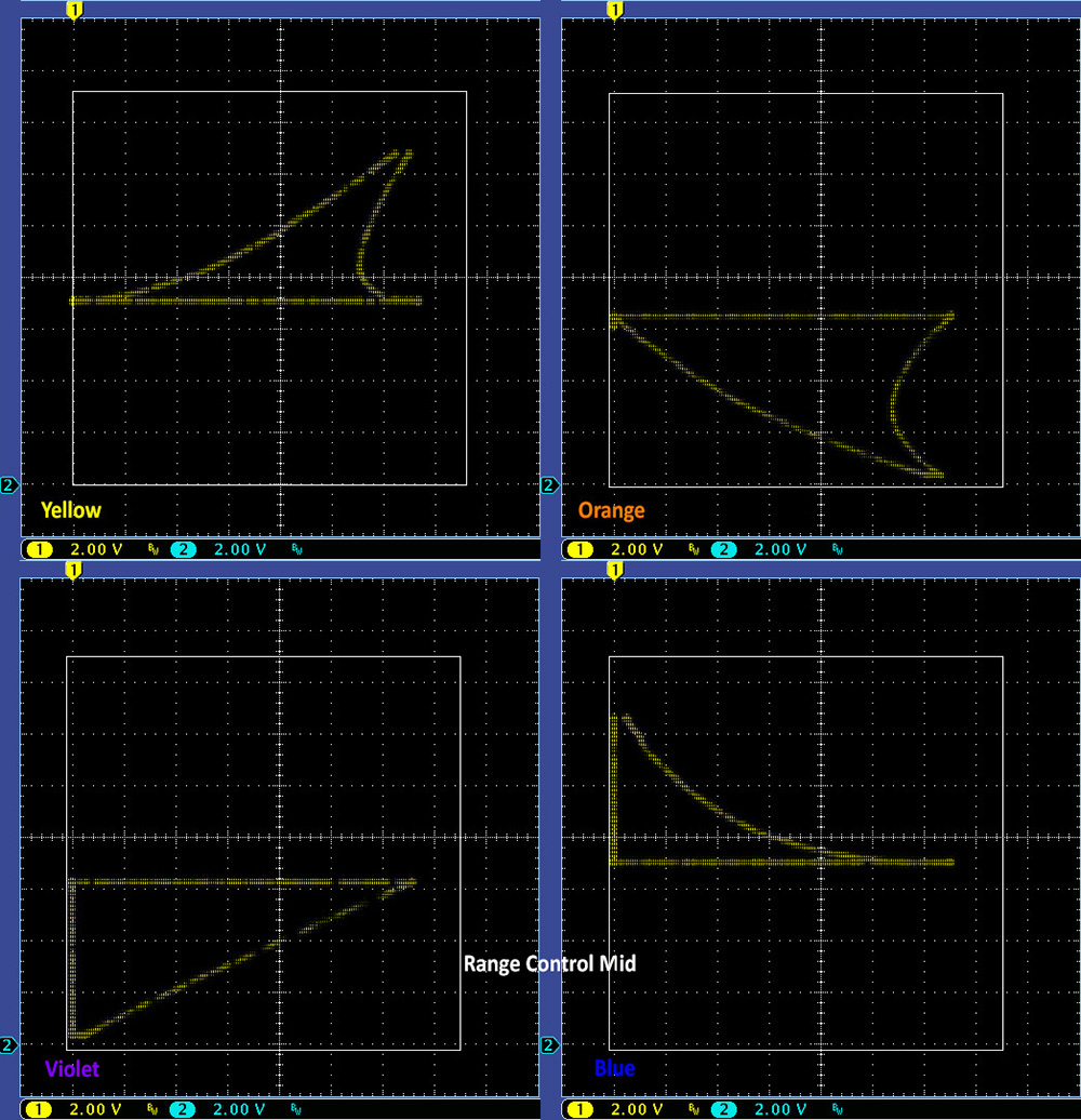
With the Range controls at max position, the orange outputs control the upper right voltage space. The violet outputs controls the upper left voltage space. The yellow and blue outputs control the upper left to right voltage space.

Another way of looking at this is to have full control of the space, the yellow and blue channels should have the Range controls at CCW and the orange and violet channels should have the Range controls at CW. This way yellow controls the lower right, orange controls the upper right, violet controls the upper left, and blue controls the lower left voltage spaces.

These outputs are in the 0 to ~12.5V range. The 227 operates with an Assign CV of 0 to 10V. Going above 10V can start to bleed to the other channels. I lowered the output range to 0 to ~10V by dropping the output feedback resistors from 100K to 82K.
I patched the CVs straight across to the 227M (see that page for info), so Yellow to channel 1, Orange to channel 2, Violet to channel 3, and Blue to channel 4. The 227 X input maps A to D or B to C. The Y input maps A to B and D to C. In the following descriptions I use the 227 orientation of A as left-rear, B as left-front, C as right-front, and D as right-rear. These following descriptions are of a general nature. As the signal moves to more than one channel, the gain for all generally decreases.
Yellow Channel Operation
The Range control is set to CCW. With the cross-pan control at CCW, the Balance control moves the signal from left-rear to right-rear. With the Balance control at CCW, the Cross-Pan control moves the signal from left-rear through all channels to right front. With the Balance control at CW, the Cross-Pan control moves the signal from right-rear to right-front.
Orange Channel Operation
The Range control is set to CW. With the cross-pan control at CCW, the Balance control adds the signal at left front to right-front and right-rear. With the Balance control at CCW, the Cross-Pan control moves the signal from left-front through all channels to right-rear. With the Balance control at CW, the Cross-Pan controls moves the signal from left front, right-front, and right-rear to just the right-rear.
Violet Channel Operation
The Range control is set to CW. With the cross-pan control at CCW, the Balance control adds in the signal at left front to right-front and right-rear. With the Balance control at CCW, the Cross-Pan control moves the signal from left-front to left rear. With the Balance control at CW, the Cross-Pan controls moves the signal from left front, right-front and right-rear to left-rear.
Blue Channel Operation
The Range control is set to CCW. With the cross-pan control at CCW, the Balance control moves the signal from left-rear to right-rear. With the Balance control at CCW, the Cross-Pan moves the signal from left-rear to left-front. With the Balance control at CW, the Cross-Pan moves the signal from right-rear through all channels to left-front.
Changing the Range control to other settings limits the voltage range and the Balance and Cross-Fade controls have various nuances that are probably best left to suit when operating in an actual quad sound setup.
Switches and Modulation Inputs Operation
The switches select the A inputs (left), B inputs (middle) or C inputs (right) jacks as the modulation source. These voltages modulate the effective position of the Range control. The left input modulates the left Yellow, right Orange, left Violet, and right Blue outputs. The right input modulates the opposite output so the right Yellow, left Orange, right Violet, left Blue outputs.
I do not have a 227 nor a quad sound setup but it would be fun to play with this in that setup.