|
155M Dual
Integrator |
|
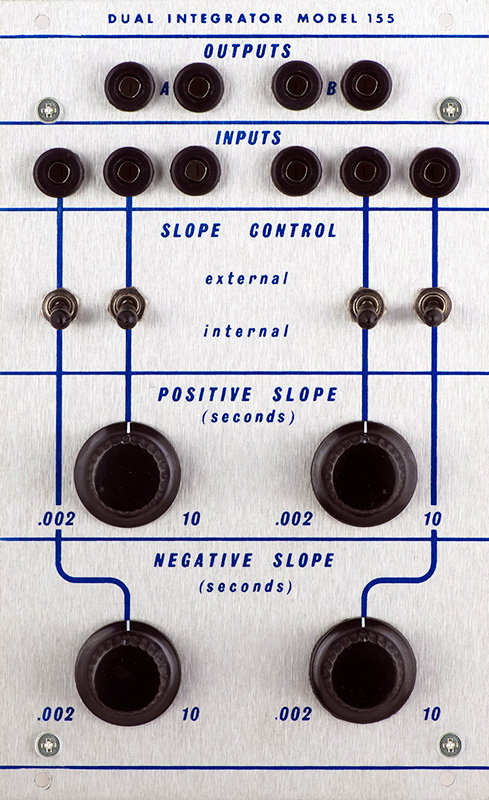
The 155 is a dual integrator that is powered by +15V only. There are separate positive and negative slope controls which may be switched out for external CVs. The slope is adjustable up to 10 seconds.
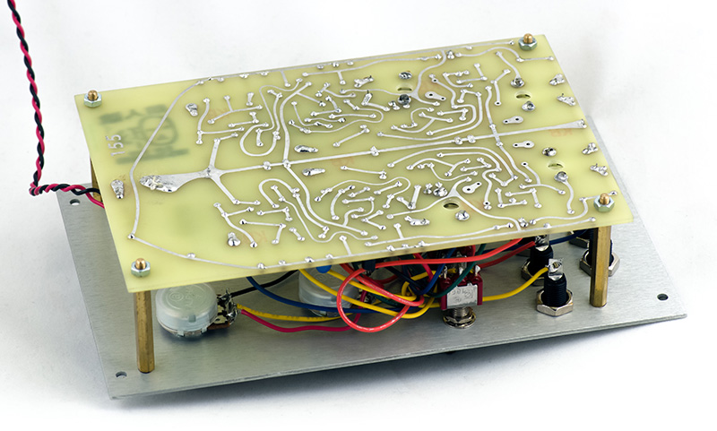
The PCB has traces only on the rear.
Operation
The controls and CV have very little impact until higher voltages. In addition, the impedance changes between internal and external so the same CV will not necessarily give the same slope.
I did a verification of external CV vs. slope with a quick visual on the scope and external CV. I wanted a general feel of the response and you can see most of the desired operation is in the 8 to 15V range.
| CV | Delay |
| 0V | 1.8 mS |
| 1V | 1.9 mS |
| 2V | 2 mS |
| 3V | 2.1 mS |
| 4V | 2.8 mS |
| 5V | 3 mS |
| 6V | 4 mS |
| 7V | 5.2 mS |
| 8V | 8 mS |
| 9V | 13 mS |
| 10V | 30 mS |
| 11V | 75 mS |
| 12V | 225 mS |
| 13V | 600 mS |
| 14V | 2.2 Sec |
| 15V | 10 Sec |
Modifications
The base of Q2 sits about 9.8V and the base of Q4 sits about 4.8V so it takes significant CV to get usable slopes. I thought of a variety of ways to modify this and ended up adding a buffer with offset between the control/Ext CV and R12/R38. This also provides a uniform impedance to the circuit eliminating the difference between the control and external CV.
I used a Norton amplifier as it has the benefit of single supply operation and ability to sum voltages in a non-inverting configuration. Only 3 resistors were required and a single LM3900 handles all four inputs. I biased the Norton output to 7.5V and compressed the 15V CV input to a 6V range so the effective CV to R12/R38 is 7.5 to 13.5V.
I chose to calibrate this to 10 seconds for a 10V input. As such the trimmers are at their extreme and I had to lower R12/R38 to compensate since the Norton amp saturates at 13.5V. With a 15V input the maximum slope should be 15 seconds (as an aside, slope should be calibrated in mV/mS or V/S).
Although I calibrated with a 10V input, I left the CV input a 15V range. This can be decreased to a 10V CV range simply by changing the gain of the Norton amp so 10V compresses into 6V. A 82K5 input resistor should do the trick (unverified). In addition a resistor of half the value of the control should be added in series with the CW terminal to drop it also to 10V.
I also changed C1 from a tantalum/electrolytic capacitor to a film capacitor to minimize leakage.
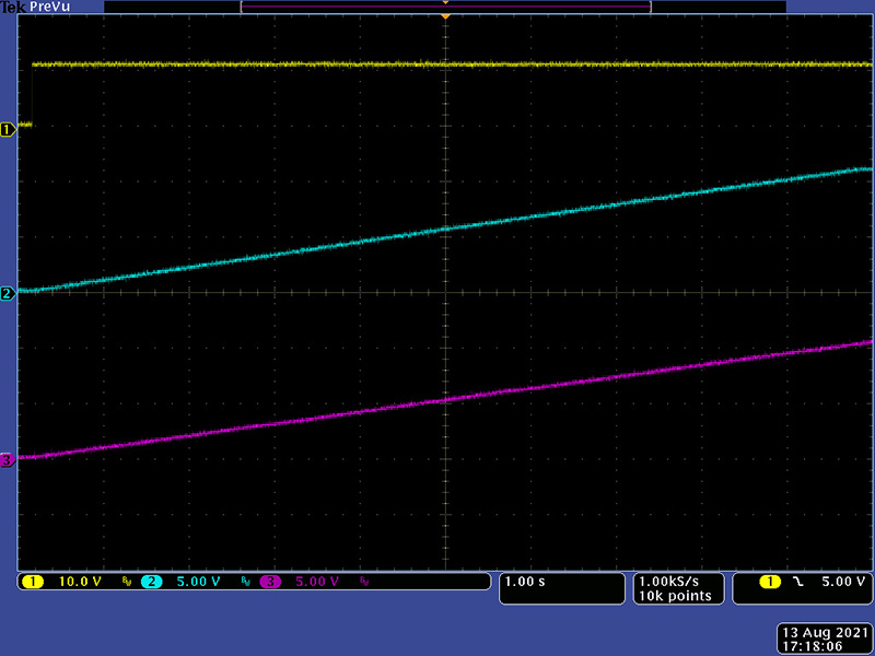
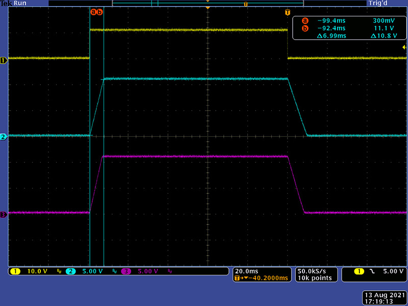
This is the positive slope set to 10 seconds with a 10V input.
This modification also affects the minimum slopes although they are so small as to be negligible. The minimum positive slope is 7 mS.
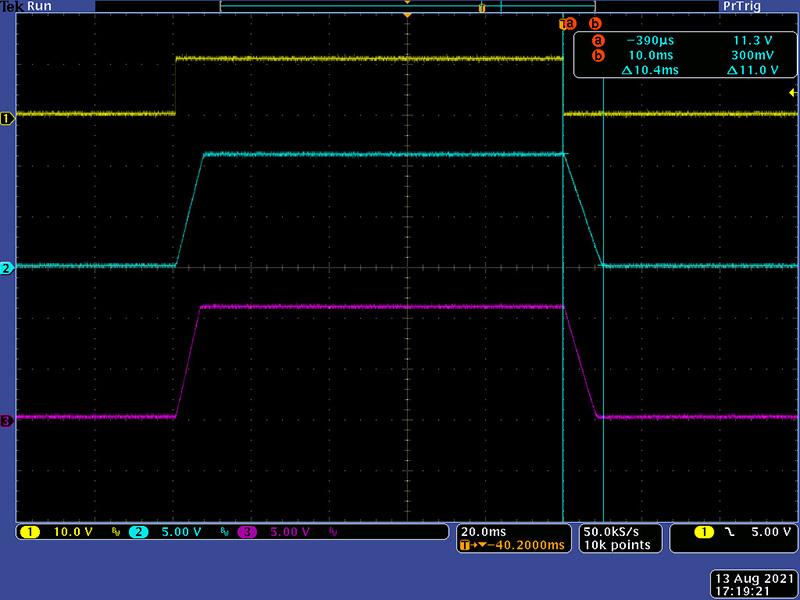
The minimum negative slope is 10.5 mS.
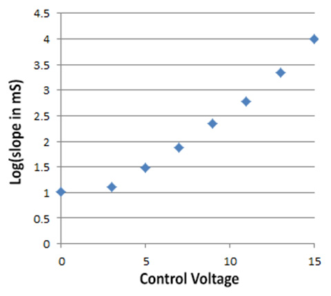
I didn't remeasure the delay after the modifications but I can map the CV input to my measured slopes for half the values albeit with some error due to the change in R12/R38. When plotting the log of slope against CV it is fairly linear showing a nice exponential response.