|
150M
Frequency Counter Module |
|
This description is from the MEMS 150 Frequency Counter page:
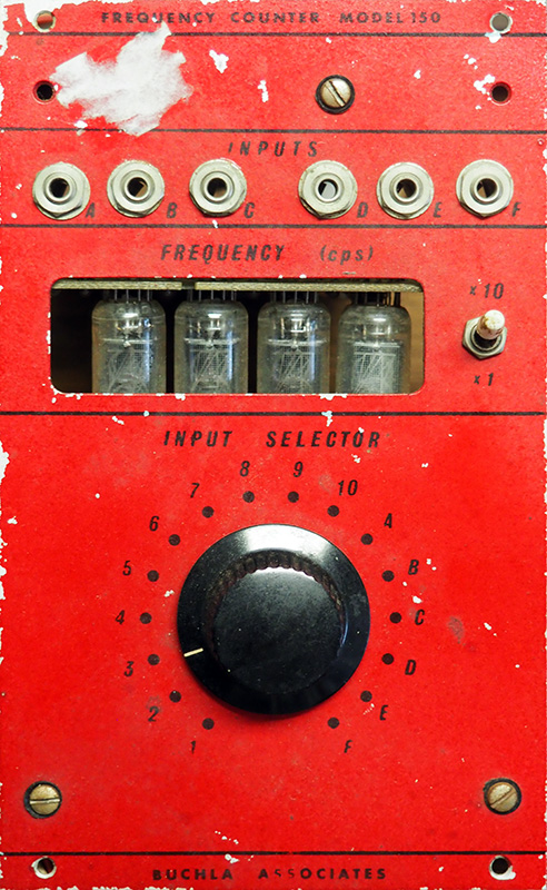
The 150 is not actually Don's complete design, more than likely it was a one-off commission for what was to be Owsley Stanley's red paneled system. Instead of designing a TTL logic based frequency counter from scratch, Don opted to hack apart a HP Frequency Counter and repurpose it for the module.
Four nixie tubes display the frequency of up to 16 selectable inputs, 6 from the front panel, and the other 10 from a rear connector.
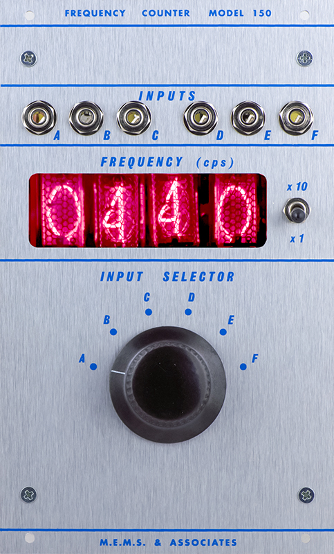
The MEMS replica is a modern design utilizing four Nixie tubes. The input selector is limited to the 6 front panel jacks but the module is true to appearance otherwise.
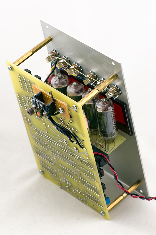
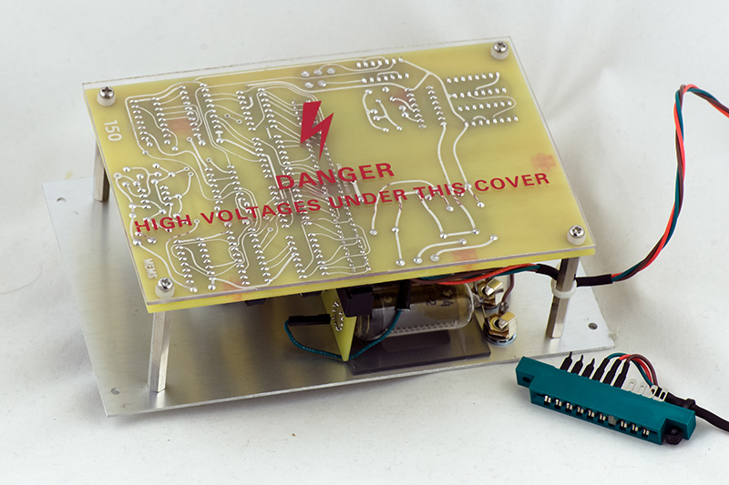
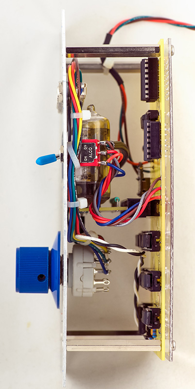
This photo shows the construction with a logic PCB parallel to the panel and a short Nixie plug-in PCB. The high voltage DC-DC converter is mounted on the rear.
The input impedance is 100K, similar to other modules. I set the reference voltage to 0.35V with 50 mV of hysteresis since the high voltage inverter does add a bit of noise to the signals. For a bipolar signal, a 800 mV pk-pk or greater signal is required. For a unipolar signal, the minimum level needs to be in the range of 0 to 300 mV and the maximum level in the range of 400 mV to 15V. This allows the frequency counter to display looping envelopes or pulses from a module like a 281 or 284. Negative inputs up to -15V are not an issue.
The counter is DC coupled so can go from 1 Hz to 9999 Hz in the X1 mode. In the X10 mode the sampling period is 1/10 Hz so the display is faster but missing the least significant digit. I didn't check for the maximum frequency but it easily will display up to 20 KHz, a suitable range for a synthesizer.
My 150 Frequency Counter Module
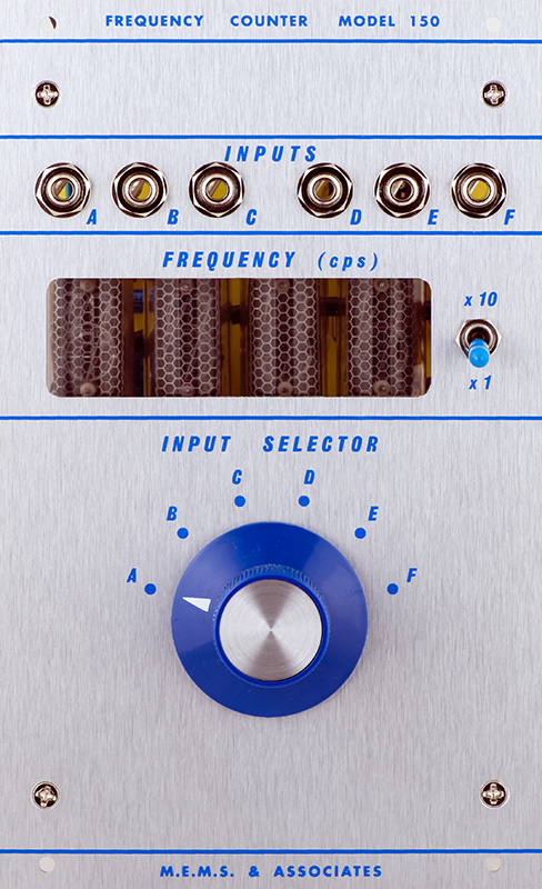
I built a 150 Frequency Counter for myself. It is the second revision of the PCB which incorporates some changes. I prefer my Nixie displays to be orange, so I used a light smoked color piece of acrylic instead of red.
I had a piece of clear acrylic with a silk screened warning from a Tektronix high voltage supply and used 2mm spacers to mount it to the rear.
This photo shows the rear PCB and the Nixie PCB.
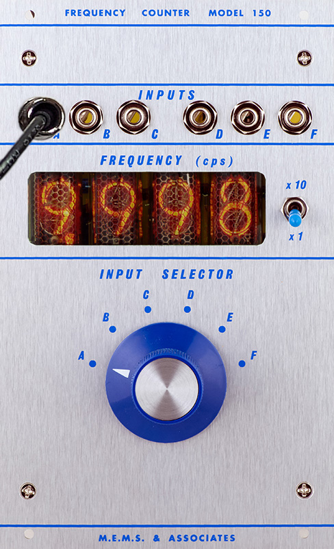
The IN-8-2 Nixie tubes have a "decimal" point, only these being Eastern European, are actually "commas". I chose to modify the X1 and X10 switch to move the thousand's display of the "comma" appropriately to indicate the range. In this image you can see a display of 9,998 Hz in the X1 mode.
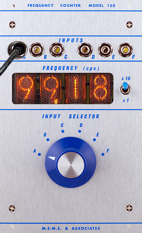
In this image you can see a display of 99,98X Hz in the X10 mode. The frequency counter operates over 100KHz but the most significant digit is missing. I did not test for an upper frequency limit.
The comparator threshold is set just a bit above 0V so both unipolar and bipolar signals can be measured. My 212 EG when patched to self-cycle has a maximum frequency of 387 Hz.
This module is 52mm deep. This module only uses +12, +5, and NG. +12V consumption is 220 mA and +5V consumption is 80 mA.