|
148M Harmonic
Generator |
|
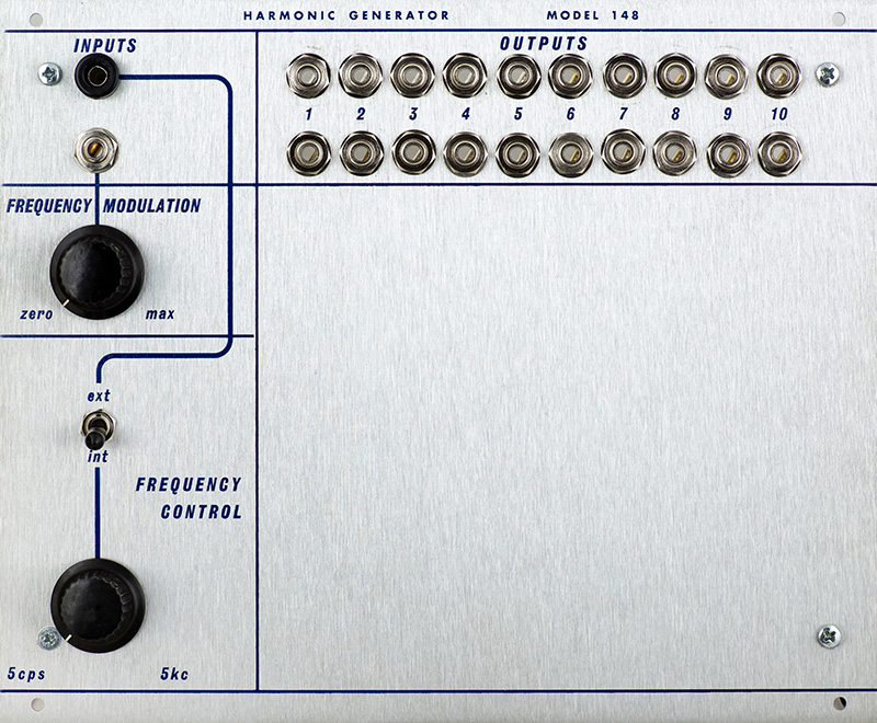
The 148M Harmonic Generator is a VCO that generates a fundamental sine wave and its first nine harmonics. Each frequency is available on its own output jack. The frequency range of the VCO is 5 Hz to 5 KHz and is adjusted by a front panel control or switched to an external CV. There is also an AC coupled FM input with an attenuator control.
The 148M requires both +15V and +24V.
Operation
The module consists of two PCBs. The main rear PCB contains the VCO and circuitry for X2, X4, and X8 outputs. It also contains two more X2 circuits for use with PCB2 for generating X6 from X3 and X10 from X5. This PCB is built with two NPN transistors in place of the µA726 exponential pair.
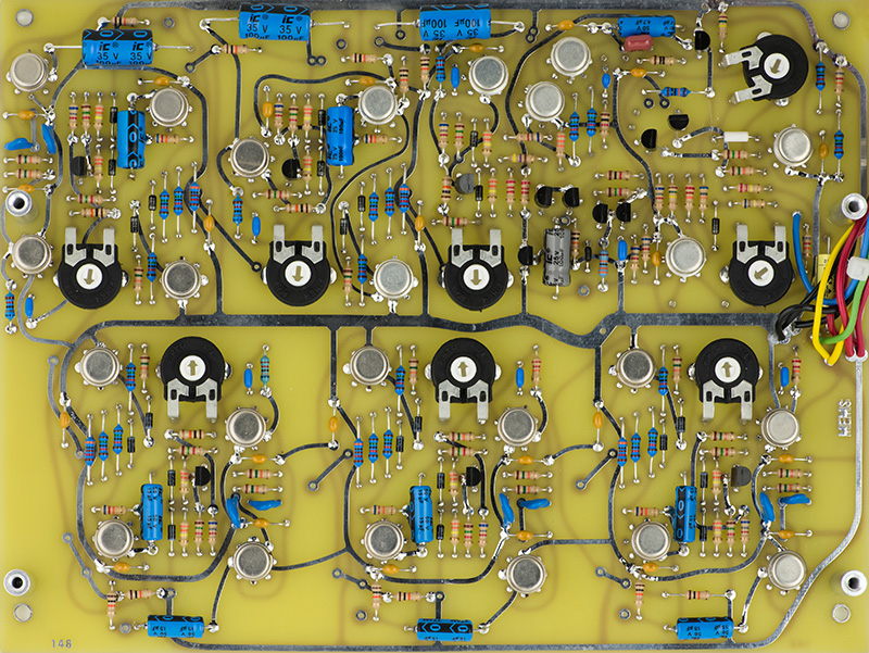
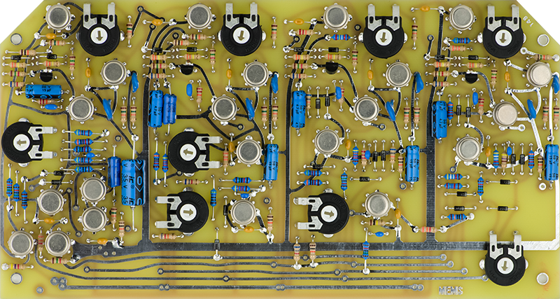
The PCB2 daughter board mounts to PCB1 and contains the circuitry for the X3, X5, X7, and X9 outputs.
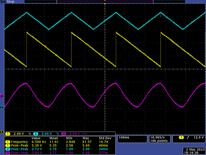
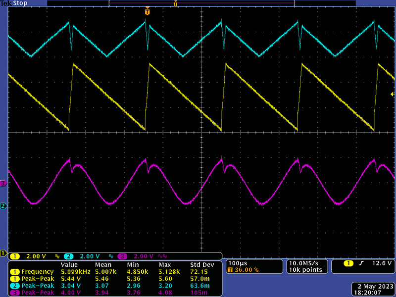
This module took a fair amount of work to operate the way I thought it should. The saw core was way too low in amplitude which I corrected by widening the reset pulse so it would reset to +15V. That increased the glitch formed by the rising edge in the triangle circuit which propagated to the sine wave output. I made some additional modifications to minimize the glitch and adjust the frequency range to 5 Hz to 5 KHz. The sine wave output was low in amplitude so I increased to a more standard 4V pk-pk output. This image shows the saw, triangle, and sine at 5 Hz.
At the maximum 5 KHz the triangle notch is of fixed duration so becomes more pronounced as the period decreases. This does propagate to the various harmonics and tends to add a timbre to the higher frequencies.
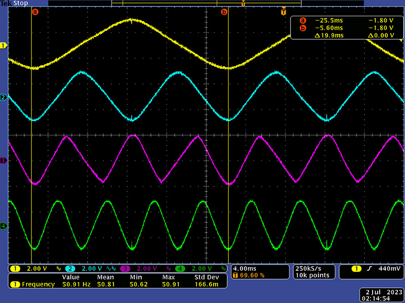
The module has three distinct circuits - oscillator, frequency doubler, and wave folders. The X2, X4, X6, X8, and X10 operate with frequency doublers. The X3, X5, X7 and X9 waveforms are generated with wavefolders. They are very sensitive to fold and clamp levels. The notch in the sine ripples through all the waveforms. I also increased the gain for more standard Buchla output levels. This scope image shows the 1X, 2X, 3X, and 4X sine outputs.
This scope image shows the 1X, 5X, 6X, and 7X sine outputs. The 7X was very difficult to tweak in. It is very dependent on the upper clamp level of 17.2V which produces a nicer waveform without the double humps. Unfortunately the upper clamp rail is 18.2V and tweaking it down to 17.2V disturbed the other outputs. I used 4 series diodes to clamp it to 15V, resulting in an effective clamp of 17.4V.
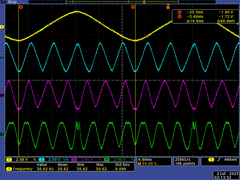
I changed the four diodes to 1N4148 which resulted in a better clamp voltage which improved both the 7X and 9X waveforms.
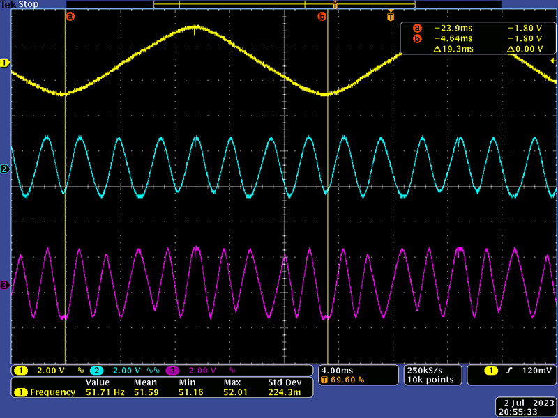
This scope image shows the 1X, 8X, 9X, and 10X sine outputs.

Summary
This is really a delicate and touchy design. I suspect each one had to be hand tweaked. I try to keep these designs close to the original as much as possible which limits the oscillator waveform and performance. How does it sound? At higher frequencies the sound has a buzziness, much like a bit of timbre. The wavefolders vary in performance across the frequency range with some cycles dropping in amplitude or out completely but but the pitch sounds quite continuous. It certainly is a harmonic generator.