 |
Jürgen Haible |
|
Note: The original Jürgen Haible website is no longer active but PCBs are being released at http://www.jhaible.com.
This is the Polymoog® Resonator module as discussed on the Electro-Music forum.
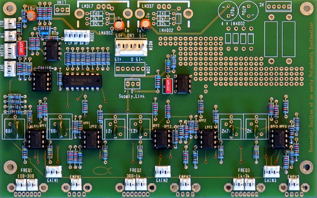
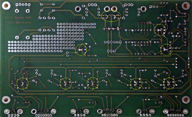
There are 10 SMT capacitors on the rear of the PCB.
Polymoog® Resonator Mouser parts list
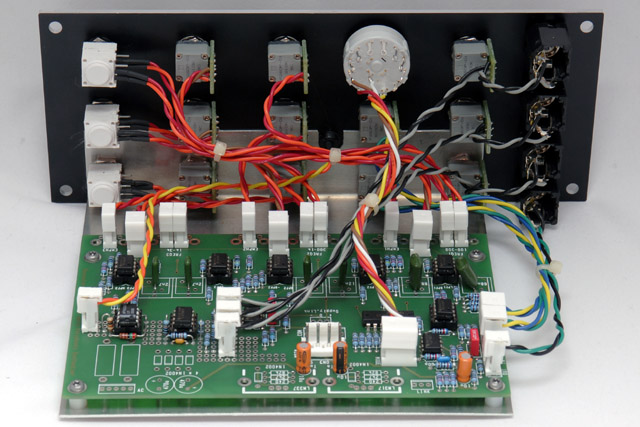
I added a three input mixer and changed the gain of the dry level to 2X (change R16 to 10K) so I could get unity gain through the module. There is a lot of gain in the resonator cells so it is easy to clip the waveforms. There is less headroom on the positive waveform since the reference (e.g. virtual "ground") is +5 volts. Some of the resonator waveforms are not symmetric so you can get either significant positive or negative clipping. I wanted an indicator that would show clipping on either end so I used a pair of comparators to form a window detect at +12.5 volts and -2.5 volts (15 volts pk-pk centered about +5 volts). The brightness of the LED indicates the amount of clipping. I built the input mixer and the clipping circuits in the PCB vectorboard area.
Power consumption: 21 mA +15, 20 mA -15
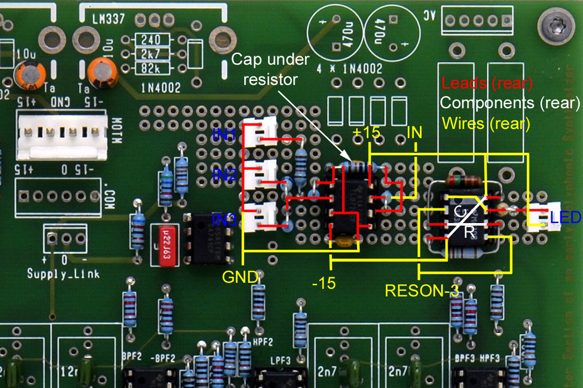
Polymoog® Resonator modification wiring updated
Polymoog® Resonator modification schematics updated
I made a bracket out of 0.050" aluminum to mount the PCB. It was nice to have the vectorboard area so I didn't have to mount a second PCB for my enhancements.
Operation
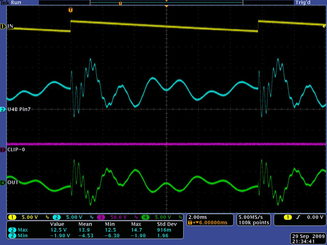
This scope image shows no clipping (magenta) on the resonance output of U4B pin 7 (cyan). The gain controls are all near maximum level while the input control has been adjusted down to 2.5 volts pk-pk.
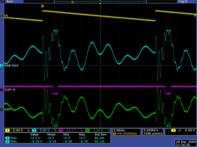
This scope image shows some clipping (magenta) on the resonance output of U4B pin 7 (cyan). The clip LED brightness varies with the duty cycle of the clip signal to provide good indication as to the amount of clipping.
The input is at about 5 volts pk-pk. I could reducing the gain controls and increase the input level as well. The increased gain of the dry mixer compensates for the larger gain through the resonance cells.
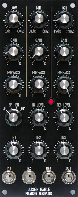
Panel
I developed many front panel designs that are shown here. This design uses small body BI Technologies and Vishay potentiometers so I could move the frequency controls (e.g. Low, Mid, and High) closer to the top edge.
|
Polymoog® Resonator FrontPanelDesign file