 |
DJB-020 |
|
I wanted a Tap-Tempo LFO module so I designed one using the Pedal Sync MV-55B Tru-Foot LFO. This chip is a "superset" of the Molten Voltage MV-52 Tap Tempo chip with program storage and recall using a Master Controller and more sophisticated functions. Check out the Molten Voltage and Pedal Sync sites for other interesting parts. The MV-55 powers up to a default program so they programmed me a MV-55B version that powers up to the CV inputs. I posted a Tap Tempo LFO topic on the Muffwiggler Music Tech DIY forum.
The analog and digital decoupling for supplies and grounds is very important. With the suggested decoupling the waveforms are pretty clean. The MV-55B requires 88 mA of 3.3V so I added jumpers to power it from either +15 volts or +5 volts.
The input circuitry sums the controls and CV inputs with schottky clamp diodes to limit the swings. Two of the controls are reversed so I inverted the CV inputs to match. I found that if the Phase input was above the MV-55B analog supply while Ratio was greater than 1:1 that the first leading edge of LFO Out after the leading edge of Tempo Out would have a very narrow glitch. This is peculiar because the inputs are specified for -0.3V to (VDD + 0.3V) and the schottky clamp diodes keep all four CV inputs within this range. I used a TL431 shunt regulator for the upper clamp diodes on the inputs and adjusted it to lower the maximum CV inputs to the MV55B and found that about 3.2V (TL431 adjusted to 2.95V) eliminated the glitch.
I added individual level shift for each output for 0 to +5 and +/-5V outputs (the 0 to +5 volt Tru-Foot / "Wah" output is ideal for driving a filter FM input). I also added current source LED drivers for indication of the polarity with green indicating a positive output voltage (in +/-5 volt mode they blink Green/Red and in 0 to +5 volt mode they blink Green/Off).
The LFO syncs quite well to the tap switch with a lowest frequency of 0.4 Hz. The first switch depression synchronizes the output and the second sets the tap frequency. The LFO will sync to a square wave signal into the Tap CV with a LED indicating the input frequency. If the input frequency is too low or two high the lack of sync can be easily seen between the Tap and Tempo LEDs.
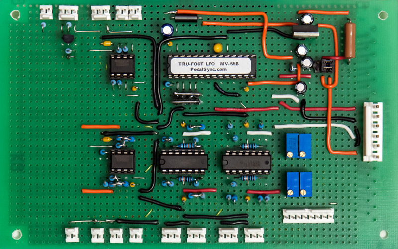
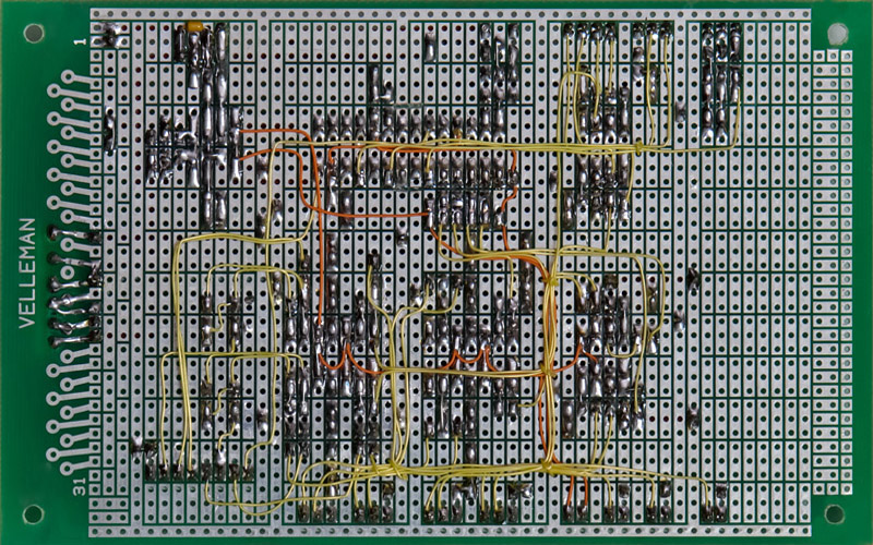
Construction
I built my DJB-020 Tap Tempo LFO on a Velleman prototype board. I added one more op-amp for the LFO-LED driver, the TL431 shunt regulator, and ferrite beads on the power supplies since this photo.
DJB-020 Tap Tempo LFO schematic Updated
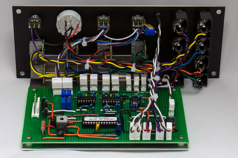
I made a bracket for mounting the proto board out of 0.050" aluminum. There was quite a bit of front panel wiring for this module. I made a small bracket out of brass to mount the trimmer on the LFO level switch.
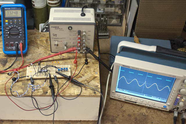
Waveforms and Controls
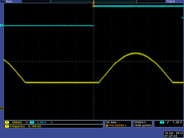
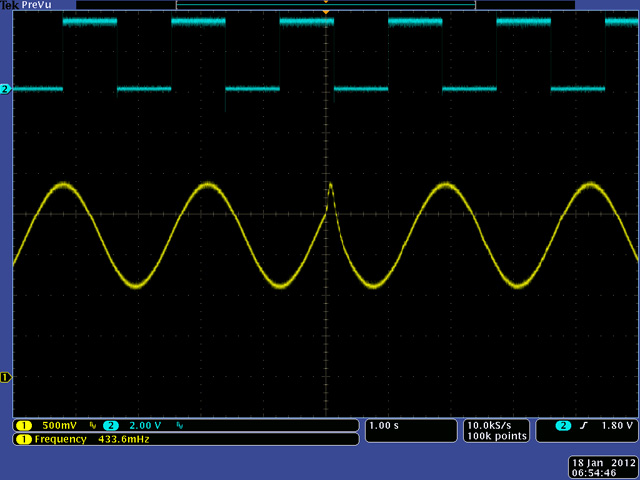
The four output modes are selected by two control pins. The cyan waveform is the quarter note clock and the yellow output is the LFO output. The quarter note clock stays "fixed" at the tempo while the LFO output is modified by the Ratio control. The Tru-Foot output is a positive half-cycle with a flat portion "pause" between cycles to simulate the control voltage of a pedal wah movement.
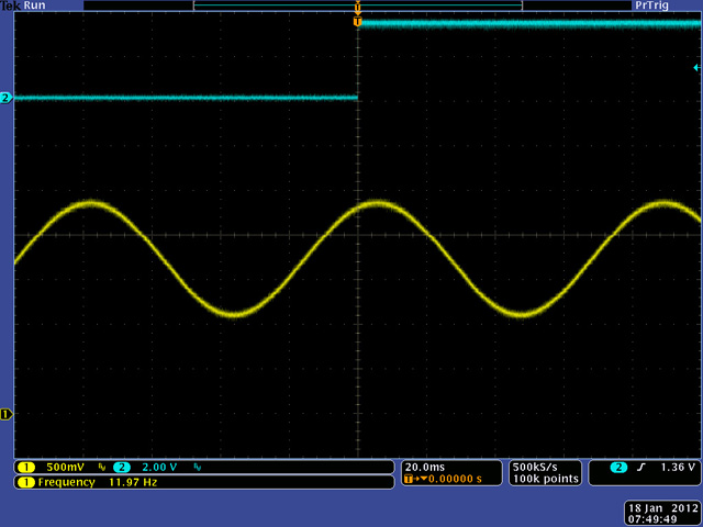
Lowering the frequency a bit shapes the Tru-Foot output to a half-sine.
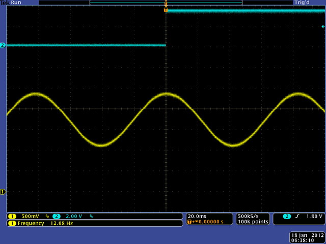
A nice LFO sine wave output.
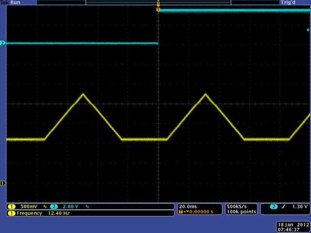
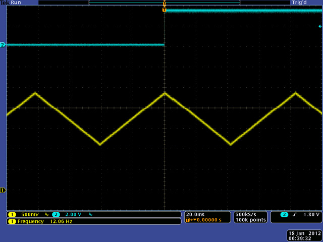
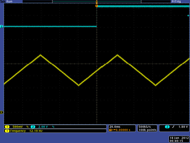
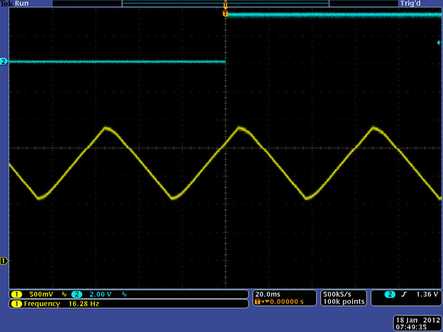
The LFO triangle output.
The Offset control shifts the phase between the quarter note output and the LFO output.
The Duty control morphs the triangle to a saw output although with not a very sharp rise. This is because the Duty control adjusts the duty cycle in 13 discrete "musical steps" of 1/20, 1/8; 1/6; 1/4; 1/3; 3/8; 1/2; 5/8; 2/3; 3/4; 5/6; 7/8; 19/20 and the output is distorted at high ratios.
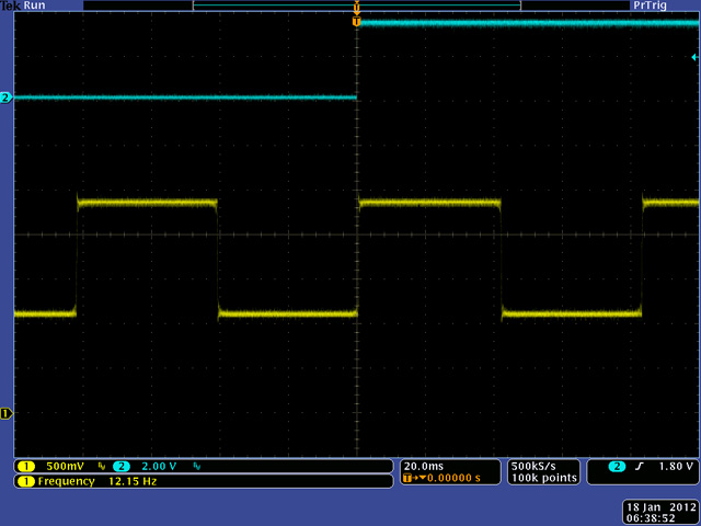
The LFO square output.
The Duty control morphs the square to a pulse output. This is the maximum duty cycle of 19/20.
Adjusting the Offset control 180 degrees inverts the LFO output mid-cycle.
Minimum and Maximum Frequency
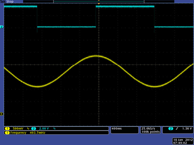
With the Ratio control set to 1:1 the lowest frequency is 0.4 Hz.
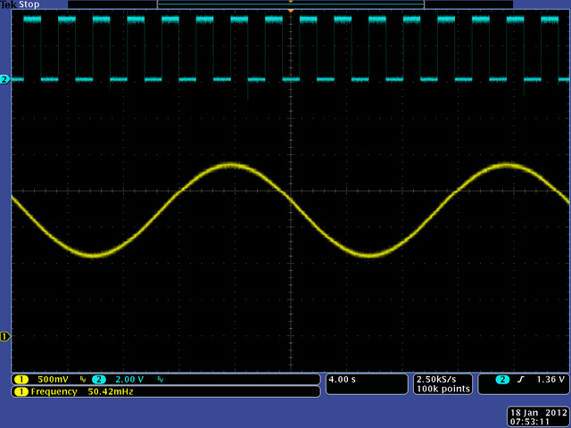
With the Ratio control set to the maximum divide (/8) the lowest frequency is 0.05 Hz. Note the quarter output stays fixed at 0.4 Hz.
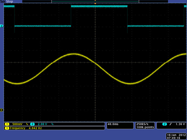
With the Ratio control set to 1:1 the highest frequency is 4 Hz.
With the Ratio control set to maximum multiply (4X) the lowest frequency is 16 Hz but the sine wave distorts as noted in the datasheet. Note the quarter note output stays fixed at 4 Hz.
Reducing the frequency down to 12 Hz restores a nice sine output.
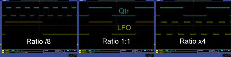
These three images show the relationship of QTR OUT to LFO OUT with the Ratio control at the two extremes.
Inputs
The four inputs (Speed, Ratio, Offset, and Duty) are 0 to 3.3V CV inputs. The pin specifications for over and under voltage are 0.3V from the supply levels so CV inputs need to be clamped to the analog supply and ground with schottky diodes for protection.
Duty and Ratio inputs are "backwards" so the potentiometers are wired "backwards" to compensate. CV inputs need to be inverted so 0/+5 volts becomes +5/0 volts. However, Duty behaves reasonably with increasing voltage increasing the positive duty cycle. The Offset control seems backwards so my input design inverts the Ratio and Offset controls and corresponding CV inputs.
You can set the tempo with the Rate control, Rate CV, Tap switch, or Tap In. The tap pin can be driven by a switch or a square wave input through an open collector buffer. The Tap In always overrides the Rate control or CV. Moving the Rate control or CV more than about 5% will then override the Tap switch or input. A single tap will reset the waveform to the beginning of the cycle, even if the frequency was set by the Rate control or CV.
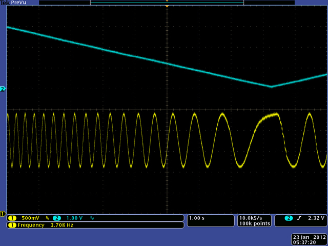
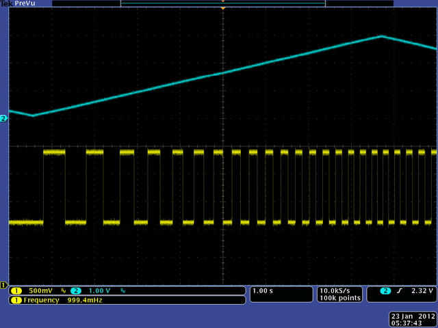
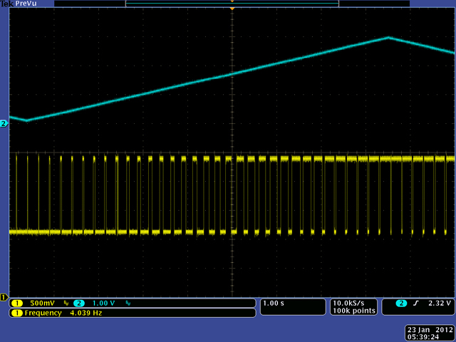
These scope images show the affects of the various CV inputs. This is the Sine Out while sweeping the Rate CV.
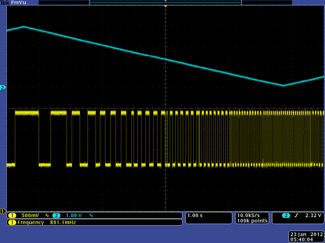
Square Out while sweeping the Rate CV.
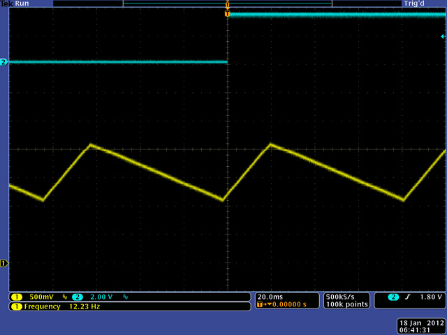
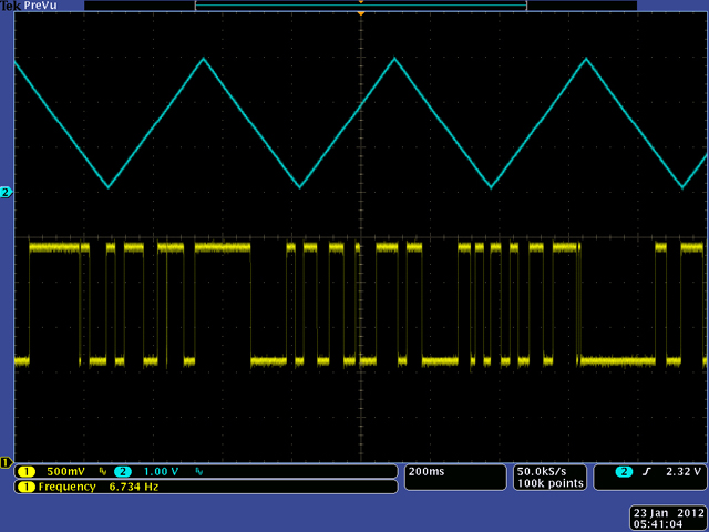
Square Out while sweeping the Ratio CV.
Sweeping the Ratio CV faster results in non-periodic transitions as I suspect the CV input sampling only occurs at distinct points in the waveform generation.
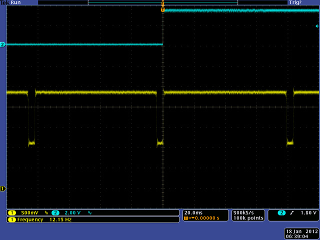
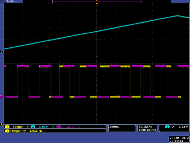
Square Out while sweeping the offset. The cyan trace is the Qtr Note Out for reference.
Square Qut while sweeping the Duty CV.
Outputs
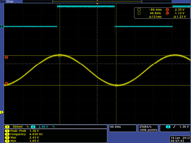
The LFO output level measured 1.38V pk-pk with a DC offset of 1.74 volts. To bring the level up to standard +/-5V waveforms it needs a gain of 7.24X with a -12V DC shift. However, the Tru-Foot output is more of a CV control so it would work best as a 0 to +5 volt output. I thought about using the waveform selection control to also adjust the gain and DC offset of the Tru-Foot output but decided to use separate level switches for each output.
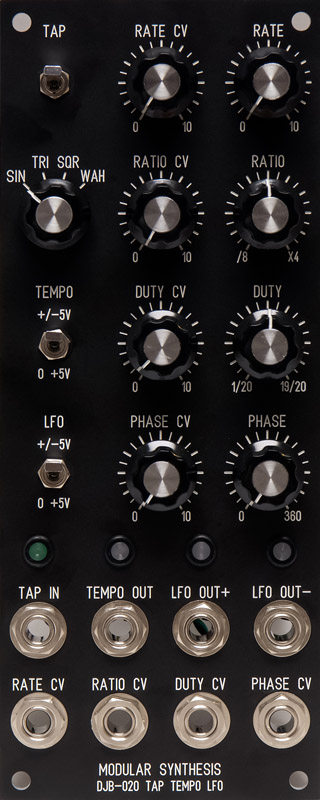
Panel
I designed a 2U panel with CV attenuators for each of the four controls, output level switches, Tap input, and LED drivers. Bi-colored LEDs above the output jacks show the polarity of the waveform. I used a momentary toggle switch for the tap input as I find it more convenient to push down rather than into the panel.
DJB-020 Tap Tempo LFO FrontPanelExpress file