|
Aries
Dannysound 129 |
|
This customer wanted a thru-zero VCO in an Aries format and chose the Dannysound 129. I needed to use three sizes of knobs to fit and designed the panel to match the layout of other similar Aries modules. The three small CV LEDs show the level of the CV jack input prior to attenuation so I mounted them in the "5" position of those controls. The large LED blinks with frequency so is useful at lower frequencies. This is a FrontPanelExpress printed panel.

The Offset control requires a bit of explanation. The Coarse and Fine controls have a limited range so the Offset is used to set the base of the range. It provides the DC reference into the Linear FM input. When this control is at 0, there is no voltage into the current source for the exponential converter, so the core stops oscillating. This is the zero point of the thru-zero operation.
Thru-zero modulation is through the Linear FM CV. If the Offset control is set high, and the linear FM CV amplitude is low, the resulting modulation may be too low to reach the zero crossing point so the phase reversal will not occur. This allows the VCO to be operated with linear FM in a non-thru-zero mode.
Since the Offset control sets the current into the linear FM input, it is best to set the control towards the higher end for best frequency stability.
The customer bought the DIY kit from Thonk and I made the bracket out of 0.050" aluminum. I chose to mount the PCBs side-by-side for debug and service. There are a lot of wires on this module and I used 0.100" MTA connectors to ease the wiring. I also made a Eurorack to Dotcom power adapter for his cabinet.
I made a few resistor changes for operation on +/-15V and a couple more for improved calibration. I used hot glue around the LEDs to make sure they are well retained in their clips. There is a lot of wiring on this module.

Operation
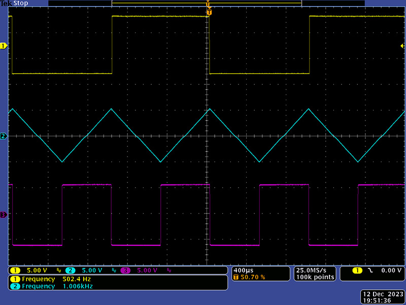
This scope image shows the waveforms at 440 Hz. The saw wave morphs with the pulse width. I set the minimum pulse width so the waveform did not disappear and that set a slight discontinuity in the center of the saw wave. With the Offset control at 0.5, the frequency range of the Coarse control is 0.2 Hz to 20 Hz. With the Offset control at maximum the frequency range of the coarse control is 25 Hz to 2300 Hz.

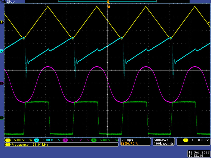
With a CV input the VCO can go quite high and the waveforms retain their shape up to about 10KHz. Above that they start to degrade and a 3V CV resulted in nearly a 21 KHz frequency as seen in this scope image. The triangle and sine still retain a good shape, the square wave is showing some slew, and the ramp waveform has degraded, although the VCO would never be used at this frequency.
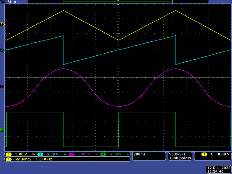
In LFO mode the waveforms are asymmetrical but achieve good shape at 1 Hz. With the Offset control at 0.5, the LFO frequency range is 0.285 Hz to 630 Hz. Increasing the Offset control to mid shifts the frequency range to 10 Hz to 950 Hz.
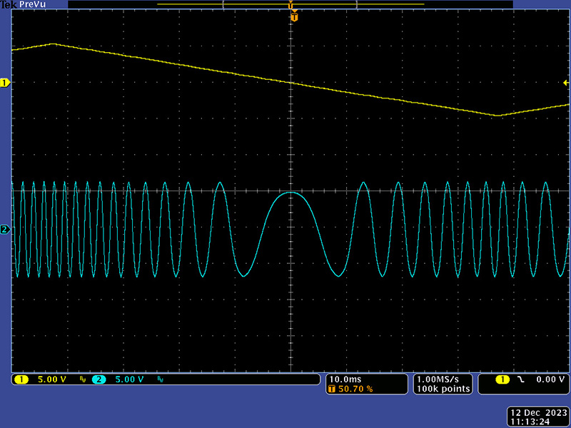
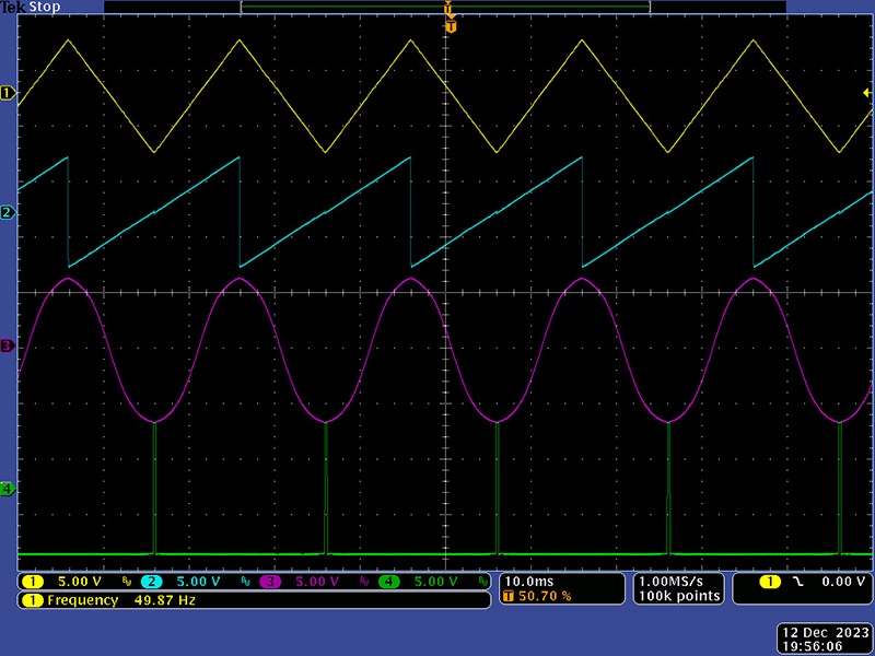
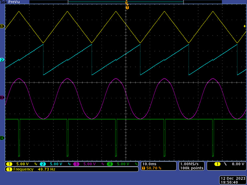
Thru-zero operation is achieved by using the Linear FM input as seen in this scope image.
These three scope images show the morphing of the saw wave and pulse width with the Saw/PW control at CCW, mid, and CW. At mid position the saw morphs to 1/2 amplitude at 2X frequency.

This scope image shows a reference frequency (yellow) and the VCO frequency (cyan, magenta) with no sync input.
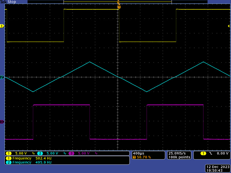
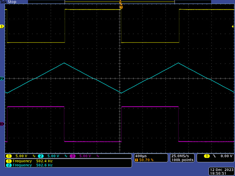
This scope image shows the same settings with sync.
This scope image shows sync with a slightly higher VCO frequency so a partial waveform begins before synchronization.

This scope image shows synchronization with a 2X VCO frequency.