 |
Aries Module Restoration |
|
I do not own any Aries modules and the only thing I have is this partial label. I do, however, repair them for others.
Aries modules were available both as kits and factory modules. Every module I have repaired appears to be a kit due to the non-uniformity of components and wires as well as some build errors. I started a new Aries Modules topic on Muffwiggler. There is some Aries information available at Synthfool. Sadly Robert Leiner's Aries site at at leinermedia.net is no longer there.
![]()
There isn't a lot of information available on Aries modules so I decided to create these pages with photos, information, and modifications. My time is equally spent tracing the circuit and finding the fault, repairing and verifying functionality, and sometimes modifying the circuit to bring it up to specifications.
Repairs are slow since I do not have PCB layout information and have to trace everything out. My initial assumption was that these modules had functioned so I was on the search for defective components. It soon became clear that there were original kit build errors and later faulty repairs. On some modules I eventually had to verify every FET and transistor type, pinout and orientation, and all component values. PCB pads have lifted with cracked traces leading to intermittent operation. These modules were only as good as the skills and talents of the original kit builder. The original soldering is varied but I have seen bridges, cold solder joints, and in one case a tin whisker! There are mechanical problems as well which shorted traces and interfered with components.
After restoration the VCO and LFO have some of the cleanest waveforms I have seen. The AR-317 is very stable and showed no signs of drifting. Its nice to see vintage modules come back to life.
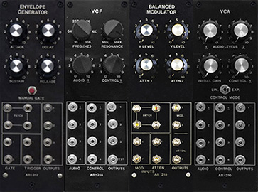
Aries AR-312 Envelope Generator
Aries AR-315 Balanced Modulator
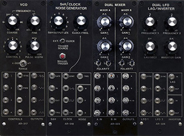
Aries AR-318 S&H / Clock / Noise Generator
Aries AR-324 Dual LFO / Lag / Inverter
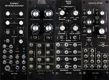
Aries AR-328 Spring Reverb & Output
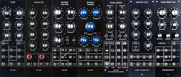
Synthesizers.com Q106 Conversion
Synthesizers.com Q109 Dual Conversion
Synthesizers.com Q115 and Q148 Conversion
Aries-format Dannysound Timbre Conversion
Aries format MOTM-440 VCF Conversion
Aries- format Dannysound 129 Thru-Zero LFO/VCO Conversion New
Aries Documentation
I assembled and corrected Aries documents for the modules I restored. Juan Bermudez, James Galambos, Michael Gilbert, and Mark Glinsky contributed documentation. I added schematics when missing and in some cases corrected schematics. However, some of the original schematics do contain errors so check for updates on my individual Aries module pages. Manuals scanned by Mark Glinsky / Manual Manor are used with permission.
AR-300 System General Information
AR-332 Dual VCO schematic (1/2 shown)
Aries 300 System Owner's Manual by Kenneth L. Perrin and the staff of The Boston School of Electronic Music
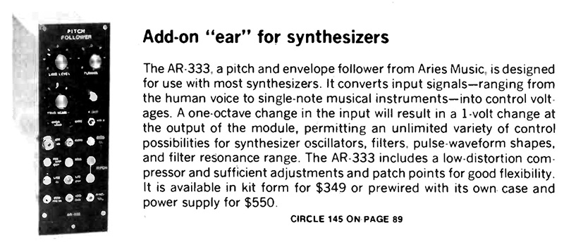
This Equipment In the News from the July 1978 High-Fidelity magazine features the AR-333.
If you have any Aries documentation not listed here, please contact me.
General Repair Tips
10V Signal Levels
These modules are designed for 10V signal levels. The AR-312 Envelope Generator would not gate at all with a 5V level but would trigger most of the time with a 5V level. It is easy to forget this if you are interfacing these modules with other gear.
2N2393 Transistors
For whatever reason, there were many more NPN transistor failures than PNP. Even the NPN in the potted exponential converter failed. These modules had previously been repaired and I needed to redo all the NTE85 transistors which had been substituted for 2N3393. The 2N3393 and NTE85 pinout is E-C-B according to the datasheet but the PCB is designed for E-B-C. A quick check of the original 2N3393 transistors have a E-B-C pinout with a dot to denote the emitter. Be careful - you need to find original datasheets that show the pinout of vintage transistors or you need to trace out the PCB from the circuit diagram.
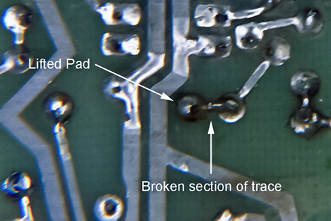
PCB Pads
There were a lot of lifted pads on the PCB and some had hairline cracks that were difficult to find. There was even a tin whisker shorting adjacent traces.
Mechanical Problems
The PCB slides into two plastic rails mounted along the edges and is secured with two angle brackets and screws. There were several instances of mechanical interference between the chassis and PCB components.
|
|
The AR-324 sawtooth amplitude trimmer was smashed into the plastic bracket so it couldn't be adjusted. |
| The AR-318 angle bracket shorted to a lead on Q1. |