|
WASP Synthesizer |
|
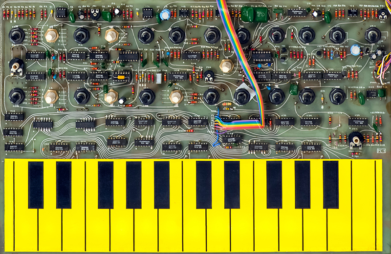
I've had to repair a couple of these WASP synthesizers. Every time I work on them I am more amazed at what they accomplished in so little circuitry. The VCOs are analog designed around a pair of 555 timers. The analog VCOs allow voltage controlled modulation. These VCOs are then converted to digital to divide down to note frequencies as controlled by the keyboard. The note frequencies are then run through a phase lock loop so that glide can be added. The output of the phase lock loop is then waveshaped for the final oscillator output. What a lot of work but it kept the circuitry very inexpensive.
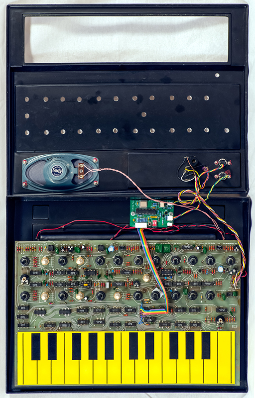
The PCB is just sandwiched between the top and bottom cover with foam strips supporting it. With age the foam has deteriorated so I always replace it with some 1/8" x 3/4" adhesive-backed open cell foam strips.
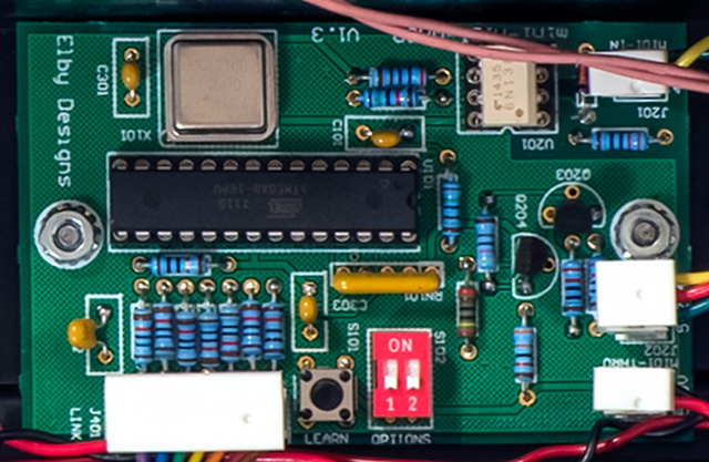
The plastic enclosures of the WASP tend to be broken but this particular one is in great condition. The small PCB is the Elby Designs miniMIDI-WASP interface that I added for the customer which provides MIDI note control over three octaves.
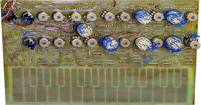
The PCB is double sided but without plating so both sides of the PCB have to be soldered. This makes it a bit challenging when adding a socket which I sometimes do for repairs. I soldered 30 gauge wire on the top trace and fed it through the hole, added the socket, then soldered the wire and the socket on the rear.
The only thing on the rear of the PCB is switch wiring and dual potentiometer wiring. I added the red/black power supply wires across the back directly to U18. U18 is a CD4016 analog switch of which two are used in the VCO and two are used in the LFO. There is some bleed through of LFO modulation in the VCO when the modulation control is at minimum. Improving the power distribution and adding a decoupling capacitor right at U18 minimized the bleed through.
This is the Elby Designs mini-MIDI-WASP interface. It replaces the DIN wiring to provide a MIDI In and Thru jack.