|
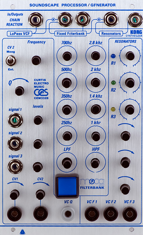
Vedic Scape Soundscape Processor/Generator Module |
|
A customer sent me his new build of a Vedic Scape Soundscape Processor/Generator. I could find no documentation on this module. The customer built it by photos as there was no BOM although part values were silk screened on the PCBs. When assembled, nothing worked. The module consists of three filters in series - a low pass filter designed around a CEM3328, a Moog fixed filter bank, and a Korg resonant filter consisting of three sections.
These types of repairs are most difficult as you don't know if the design has errors, the PCB has errors, or if the assembly was correct. The low pass filter design was fairly straightforward as it was a basic CEM3328 design. The CEM3328 did oscillate at a low level 8 MHz which took a bit to tame.
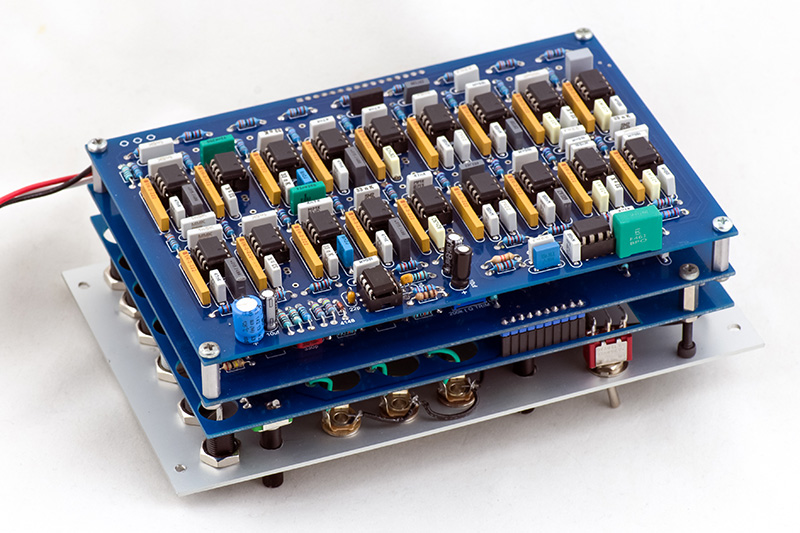
When I got to the Moog filter, I discovered an IC with no +15V, indicating that the PCB did indeed have errors. At that point I was able to locate a YouTube of the filter, and the owner Precarious 333 was gracious enough to send me photographs of the front and rear images showing the modifications. He was also kind enough to clarify a few component values as well as the switches and controls. These next images are all courtesy of Precarious 333.
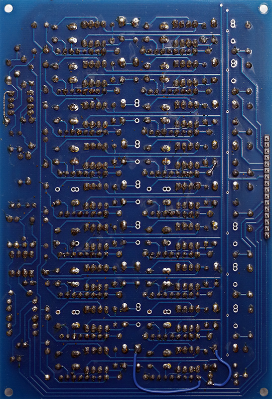
PCB3 consists of the Moog fixed filter bank. It uses a lot of identical isolated resistor networks.
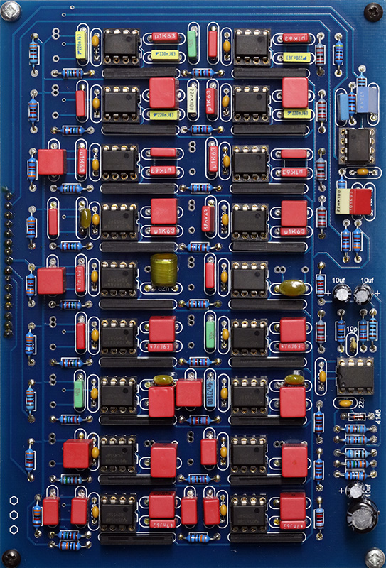
These modifications were quite useful. The wire in the upper left is the missing power. The LPF and HPF output was significantly greater so I adjusted the summation resistor values.
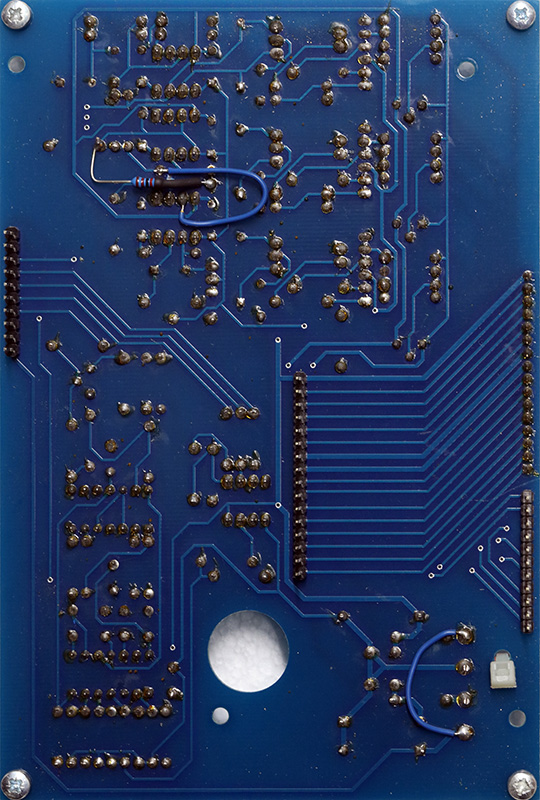
PCB2 is the LPF and resonant filter.
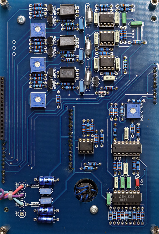
The top modifications didn't work out exactly for this particular board set. This is the summation amplifier for the three resonant filters and I had to make a few minor changes.
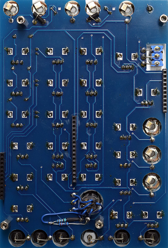
PCB1 is basically the potentiometer and jack wiring. These modifications were for the LED in the pushbutton switch. It was routed for +5V operation. In the previous image you can see where +5 is connected to +15V. The modification is to drop the voltage for the LED which is controlled by the second half of the DPDT switch.
Operation
Each filter section now works as expected. The switch for the LPF changes CV2 from the banana jack to the output of the Moog fixed filter bank. The blue pushbutton switch is a bypass for the Moog fixed filter bank. The three bottom right potentiometers are the attenuators for the three Korg CV inputs, one per each filter section.
I chose to adjust the three resonant filters with the controls set to mid at 2.8 KHz, 1 KHz, and 100 Hz. This gives a nice wide range of operation. The input jacks to the Moog fixed filter bank and Korg resonant filters are normalled so inserting an external signal breaks the chain.
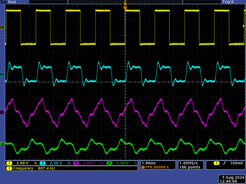
This scope image shows a 800 Hz square wave input, the LPF output with resonance, the Moog fixed filter output, and the Korg resonant filter output.