 |
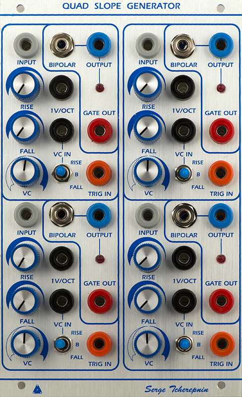
Vedic Scape Quad Universal Slope Generator Module |
|
I was sent a Vedic Scape QUSG to finish. I had no documentation for any mods required for this PCB so it was a longer build and investigate to get it all working. Once I got the first USG mods determined, the other three were the same.
Construction
This is a two board PCB set. The panel board is simply for the controls to square pins.
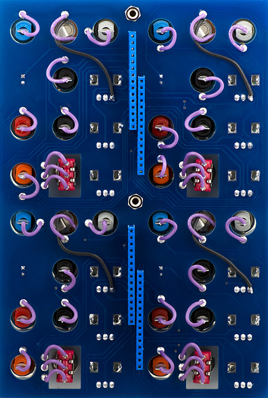
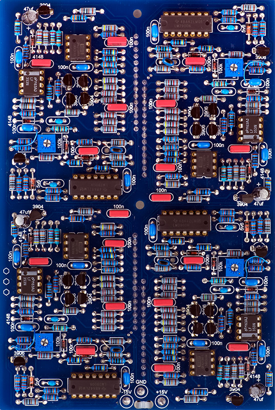
All of the circuitry is on the rear board, with the components facing out which makes debug and servicing easier. All of the semiconductor silk screens were reversed. I had to lower one resistor to make the end of cycle functional, there was one pad for the trigger capacitor that was miswired to +15V, and there was +15V missing from a component pad. The other mods were two resistor changes were to operate the bipolar output at +/-2V and a zener diode change for a 10V end of cycle signal.
Operation
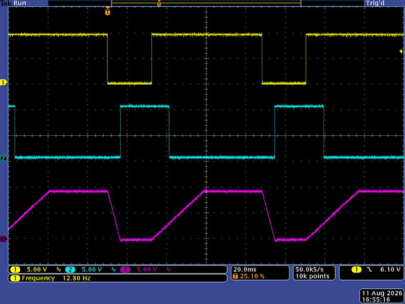
This scope image shows the basic operation with an input rectangular wave, end of cycle, and the output with a different rise and fall time.
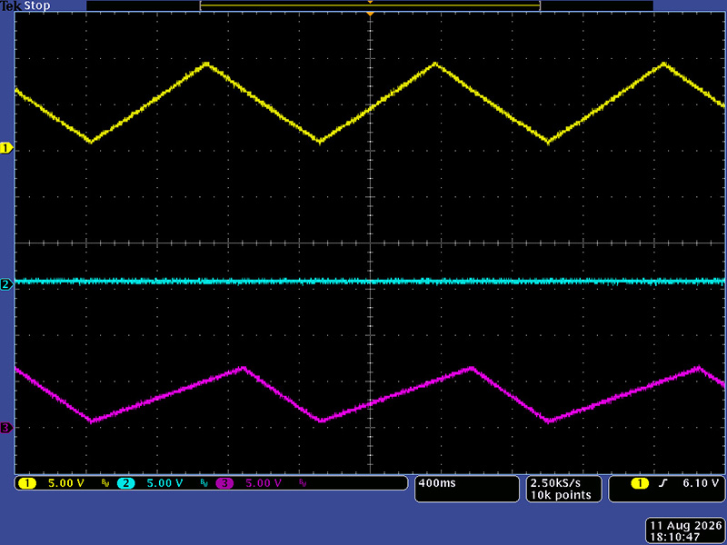
These four scope images show the USG with a non-rectangular input. This scope image shows an asymetic ramp waveform input. The USG is adjusted for rise only. Note the amplitude is reduced as it cannot reach maximum. Also, there is no end of cycle output.
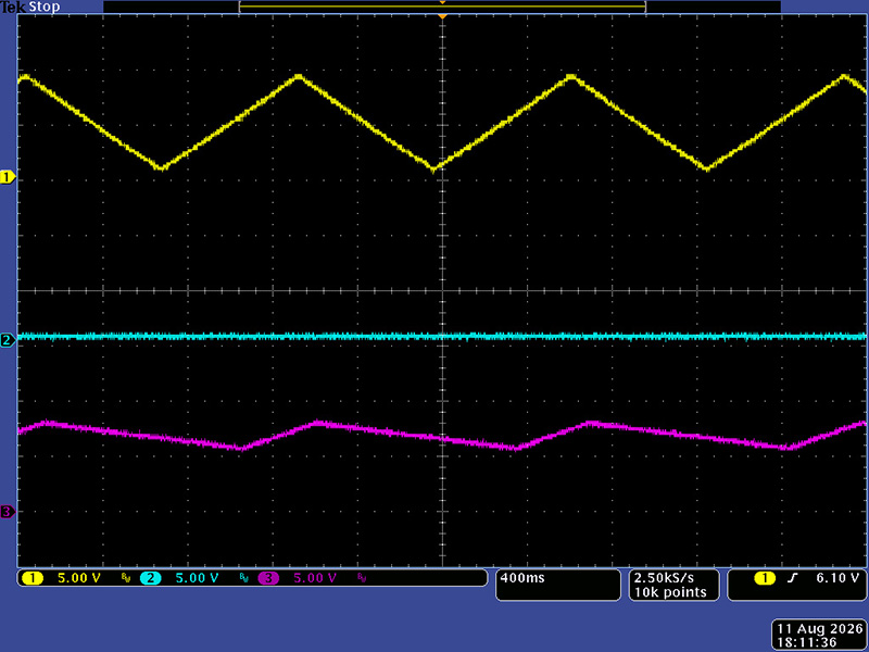
This scope image shows an asymetic ramp waveform. The USG is adjusted for both rise and fall. Note the amplitude is further reduced from both minimum and maximum voltage.
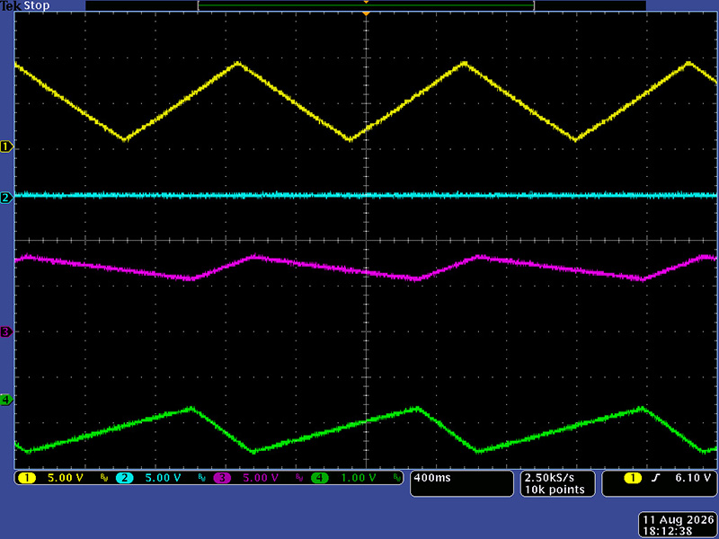
With this reduced output amplitude the bipolar output is also reduced but now offset as this is a fixed DC shift.
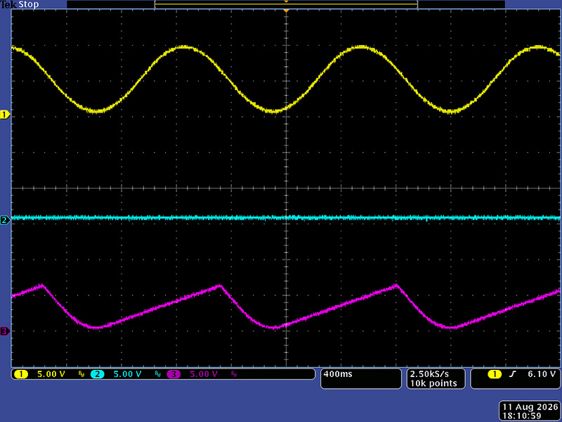
This scope image shows a sine waveform input. The USG is adjusted for rise only. The amplitude is reduced and the fall shows the sine input shape which was not as obvious in the above asymetic ramp input image.
This scope image shows the self-cycle mode at the longest rise and fall time. The CV input would increase this further but at 280 seconds I didn't want to wait. This is a 3.5 mHz waveform. The cyan is the bipolar output.
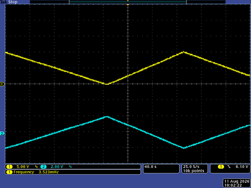
This scope image shows the self-cycle mode at the shortest rise and fall time at ~600 µS. The CV input would decrease this further. The cyan is the bipolar output.
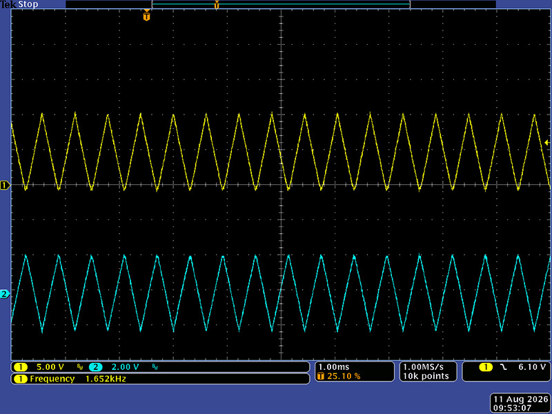
These next three scope images show the first end of cycle patched to all four trigger inputs for self-cycle mode. This scope image shows them all fairly synchronized.
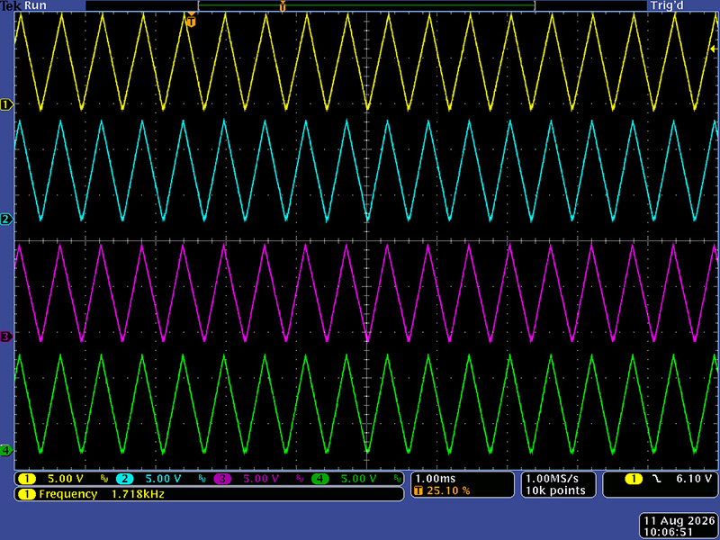
These next two scope images show various different complex cycles with differing rise and fall times.
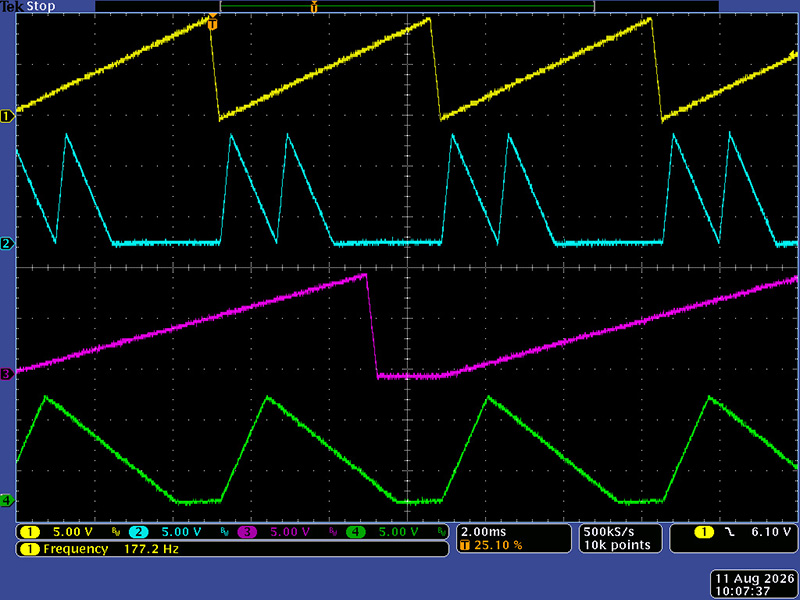
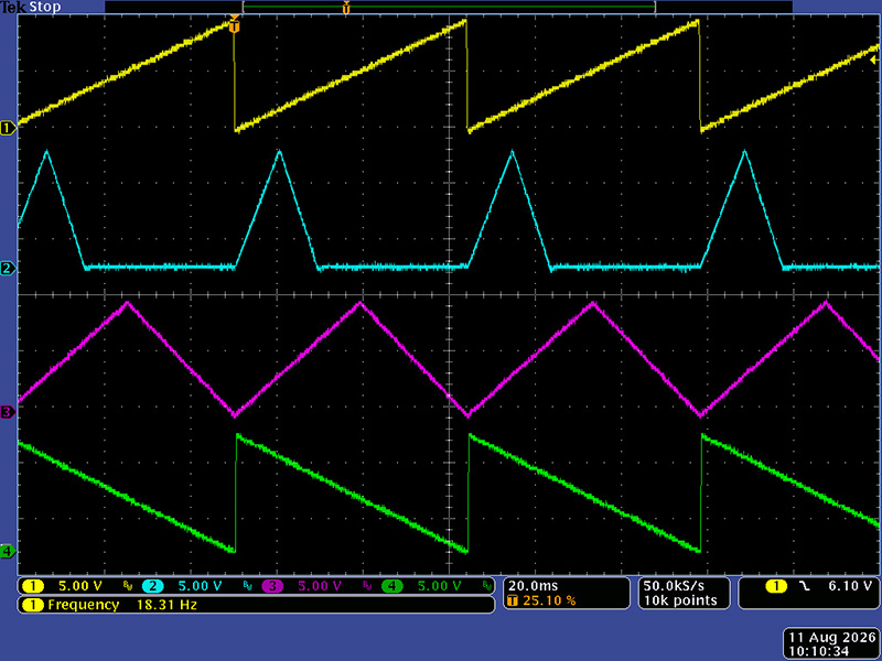
These next three scope images show the self-cycle mode with a CV input and adjusted to the CW of center. This scope image shows the mode in both.
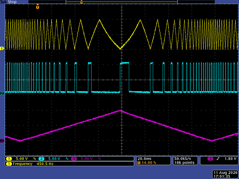
This scope image shows the mode in rise.
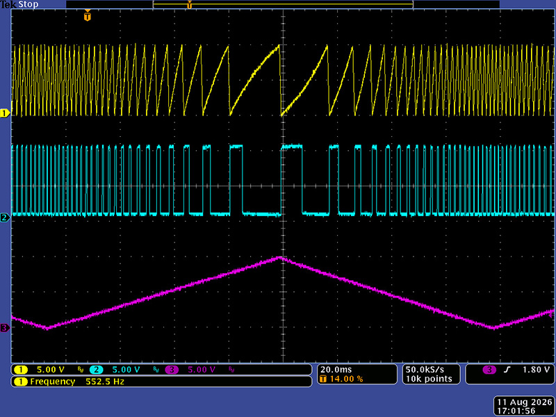
This scope image shows the mode in fall.
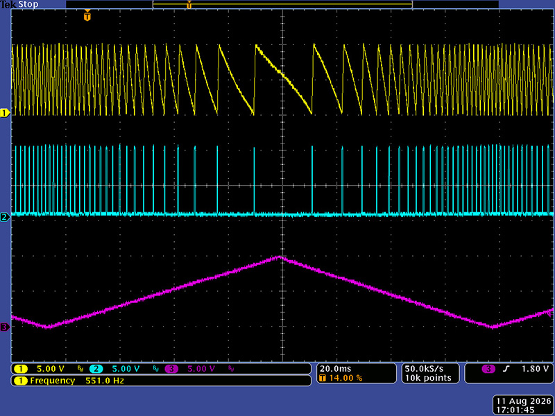
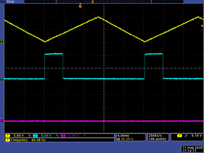
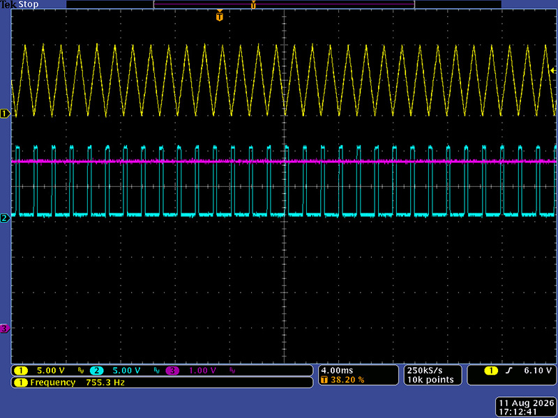
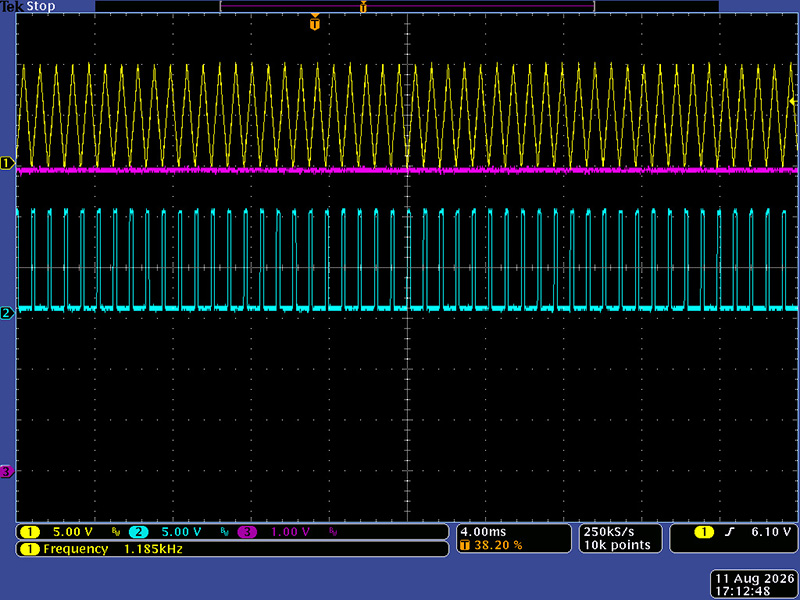
These next six scope images show the V/Oct input. Cyan is end of cycle and magenta is the CV input. This is the base frequency of 50 Hz.
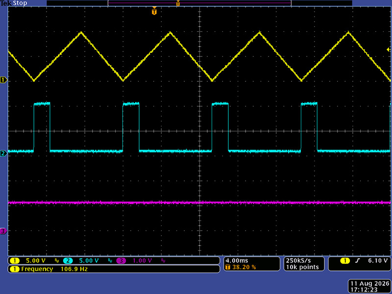
At 1.2V CV the frequency increases to ~107X, a multiple of 2.14X, so 14 cents sharp. There is no scaling adjustment and the resistors are all 1% so there is additive tolerance.
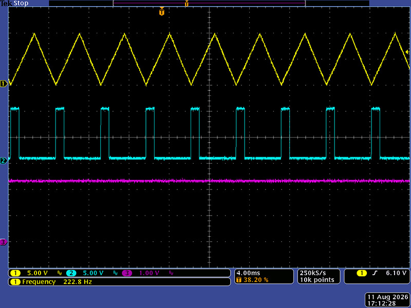
At 2.4V CV the frequency increases to 222.8 Hz, an increase of 4.45X, or an increase of 2.082X, only 8 cents sharp.
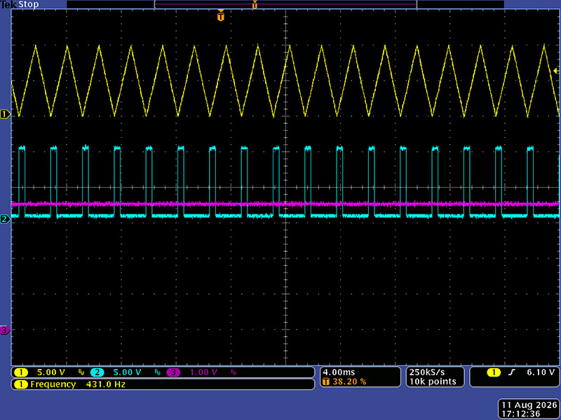
At 3.6V CV the frequency to 431 Hz, an increase of 8.62X, or an increase of 1.93X, now 7 cents flat.
At 4.8V CV the frequency to 755.3 Hz, an increase of 15.1X, or an increase of 1.75X, now 25 cents flat.
At 6.0At 4.8V CV the frequency to 1185 Hz, an increase of 23.7X, or an increase of 1.57X, now 43 cents flat. This CV input is non-linear but is close for the first 3+ octaves.
Calibration
The trimmer in each USG sets the amplitude. I operated each in self-cycle mode and adjusted for a 10V pk output.