 |
Klinkenberg Sequencer Expander Card |
|
I built a 208 Sequencer Expander card as described on the Buchla 208 sequencer expander card thread on the ModWiggler forum.
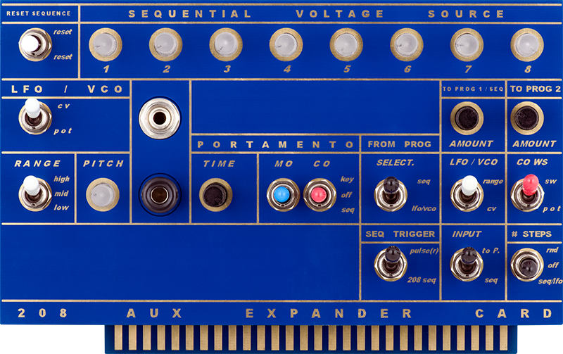
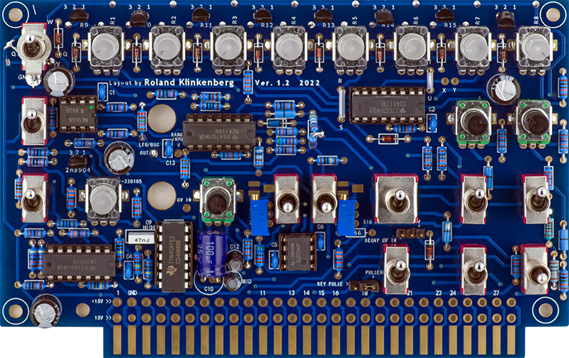
The card is a mix of SMT LEDs with through hole parts. It looks well done and has a BOM and build guide on the thread.
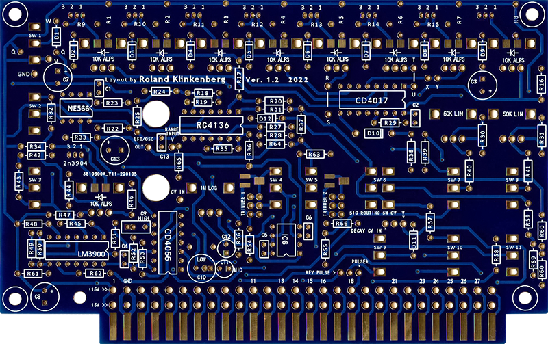
Construction is mostly straightforward in following the build guide. I found I needed to determine the cathode on the LEDs which are indicated by a black dot. I also found that Trimmer2 needs to be installed in the pads furthest away from SW5 for clearance. I do not have the expansion connector to solder yet
Calibration
I made these selections for the SOT resistors:
R59 = 111K and R60=105K
R37 = 250K for 3.6V
R25 = 21K5 and R18 = 27K
I had high frequency oscillations on the VCO on the 208 From Prog jack. The inverters for this are on card 4. The first inverter has a 100 pF compensation capacitor but the second one didn't and oscillated. I added a 100 pF capacitor on card 4 IC2 pins 12 and 14 which corrected the issue.
I did not use R166 or the optional three position header.
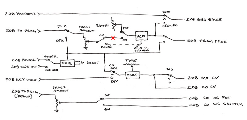
I need more of a flow diagram to understand what all the capabilities of this Sequencer Expander card is. I drew this up and believe it is correct. The red "X" marks where I added the inverter for the VCO CV.
Modifications
I made my reset switch be an On-Off-(On) with the momentary down for reset. I made the up position select 5 staged so I can run both sequencers together.
I thought it made sense to have the VCO output be both a unipolar CV and a bipolar audio level on the panel and needed to add a banana and 3.5mm jack on the panel.
The banana plug needs a small body to fit through the hole. I wanted a black surround banana jack and used Multicomp 24.247 series banana jacks, the same as on the Synton 3000 series. Even with the smaller barrel I had to insulate the exposed portion with heat shrink as it was close to the hole.
An open frame 3.5mm jack is too deep but I found a 9mm enclosed jack. It required cutting off the tabs and soldering wires inside the body to bring through the hole. I attenuated and shifted the VCO output to a 4V pk-pk bipolar signal with three resistors. It works fine with an input impedance of 10K or more.
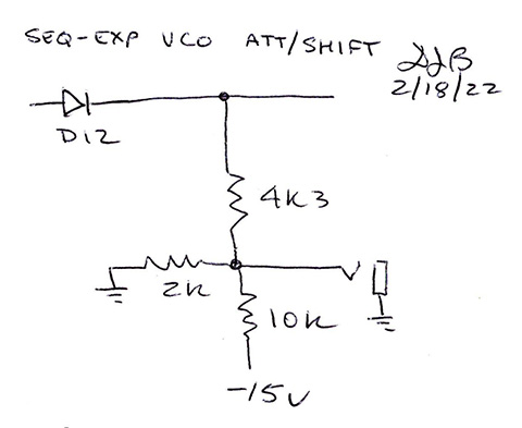
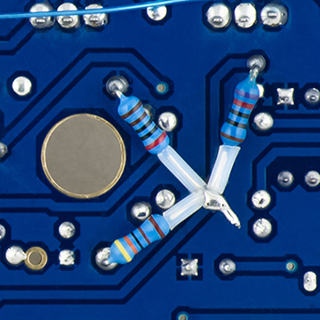
The resistors solder to nearby pads. The small lead is for the jack to solder to. The wire across the top is for my 5 stage sequence mod.
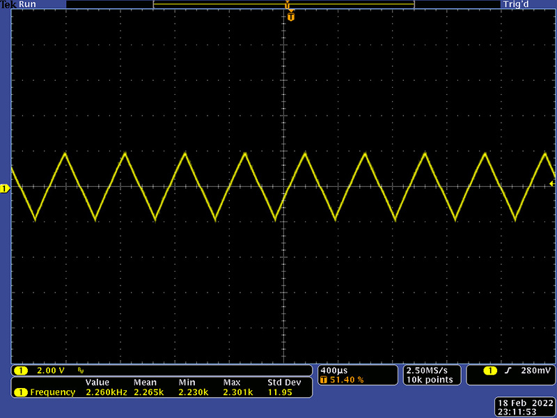
The VCO audio out is 4V pk-pk and centered about ground.
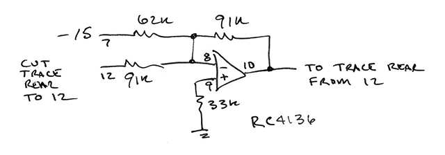
I used the left over op-amp to add an inverter for the VCO. I added it at point "X" in the flow diagram. On the rear you can cut the trace going to pin 12 of the RC4136. At this point the CV is 8.5 to 13.5V CV so the logical inverter has to shift by 22V to offset the -8.5 to -13.5V CV. The new output pin 10 needs to connect to this trace.
The CV still doesn't have the frequency range of the potentiometer but will address that after I have more experience with this module.