|
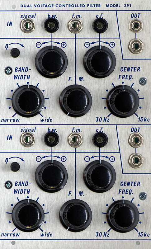
291 Voltage Controlled Filter Module |
|
I built a 291 Voltage Controlled Filter module for someone else. They sent me a complete kit of parts and I assembled and tested the module. Many of the components are sourced through Mouser but specialized parts, panel, and knobs have specific sourcing requirements.
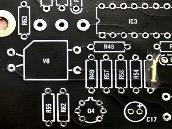
I made reference designators from the PCB images. The components cover the silk screen legends once populated which makes it hard to debug if anything is wrong.
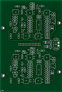
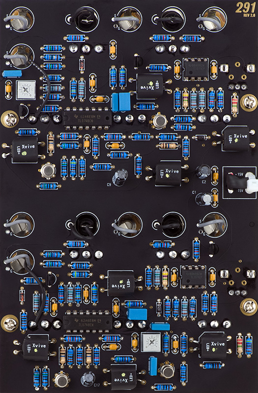
PCB 1 Front Reference Designators
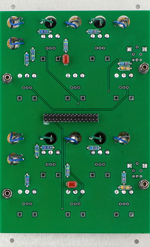
PCB 1 Rear Reference Designators
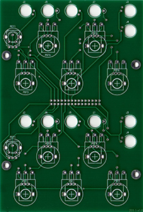
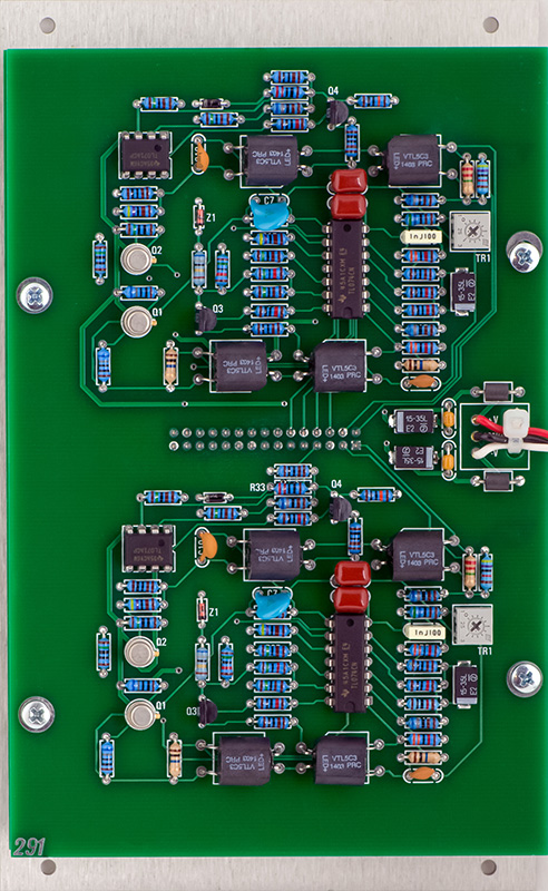
PCB 2 Front Reference Designators
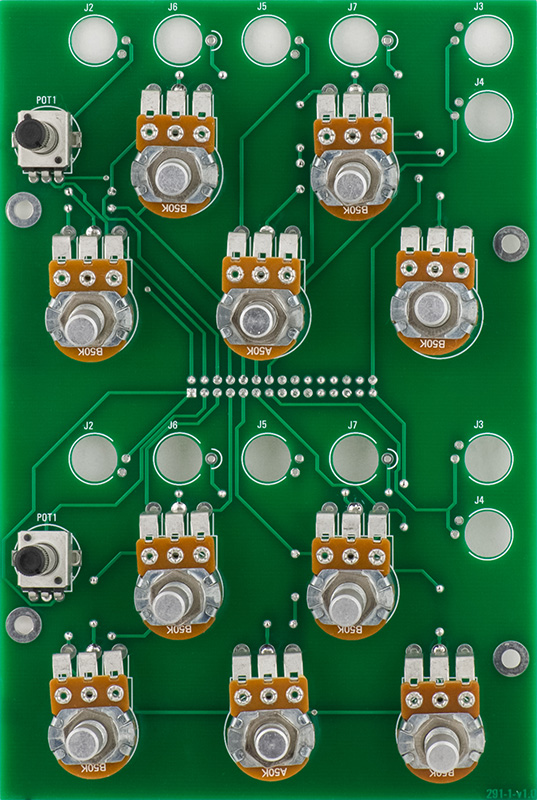
This is a fairly simple module and quick to build. The BOM is a bit confusing as there are two duplicate sections on each PCB and it is easy to order the wrong quantity of parts. PCB1 has all of the front panel controls. The potentiometers in this photo only have one pin soldered to align with the front panel for final soldering.
PCB1 also has a small number of discrete components.
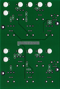
PCB2 is relatively simply and only requires +/-15V. To top right mounting hole doesn't quite line up and had to be filed lower.
Operation
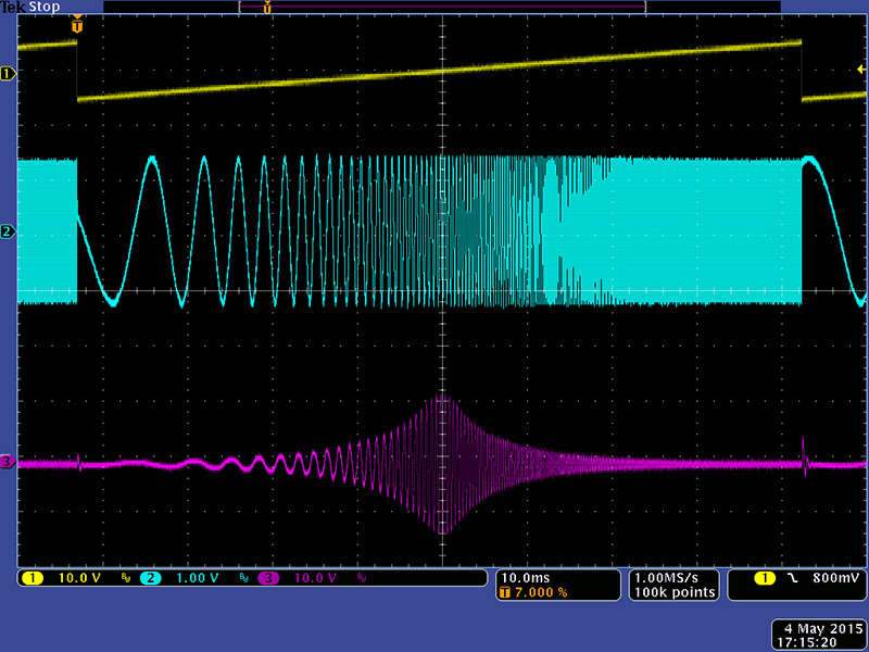
This is a dual bandpass filter with variable width, center frequency, and Q. This scope image shows a swept sine wave from 100 Hz to 13 KHz. The bandpass filter is set to narrow and centered. This filter is quite hot. Note that the input level is about 3V pk-pk and the filter output is over 20V pk-pk.
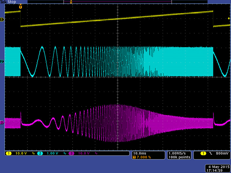
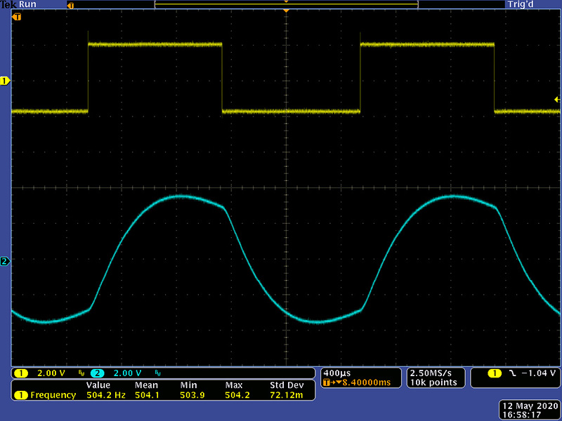
This image shows the bandwidth set to wide.
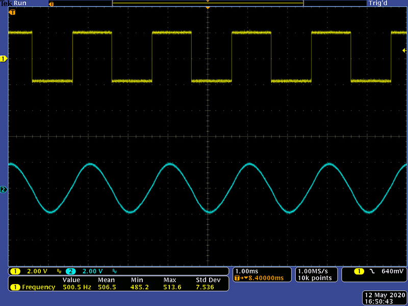
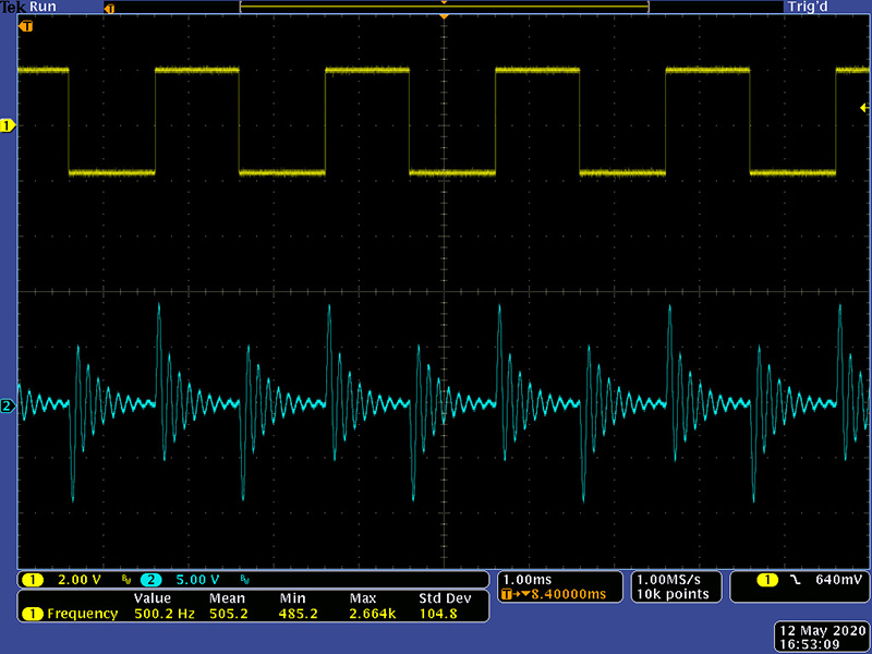
This is a square wave filtered at the center frequency.
It shows a nice sine wave fundamental.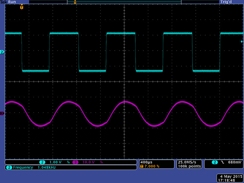
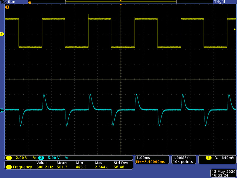
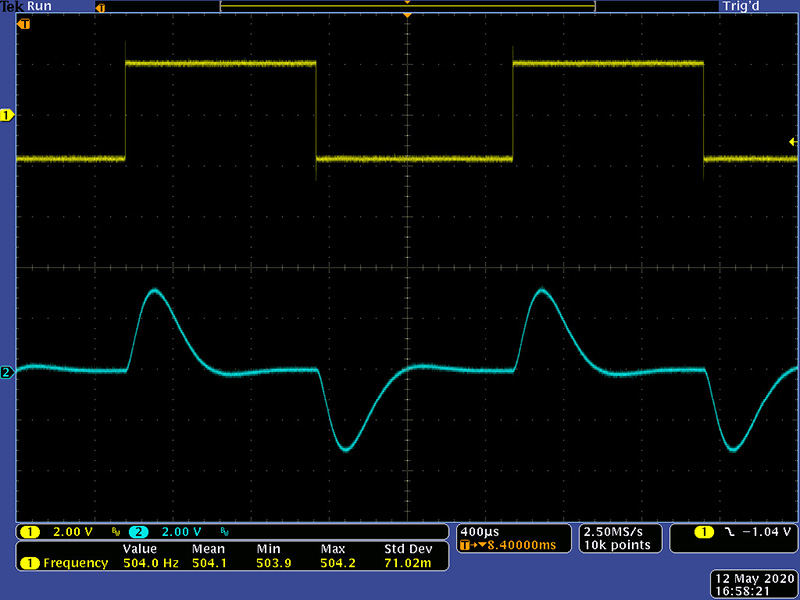
Adjusting the bandwidth and center frequency controls can morph the output with some nice timbres.
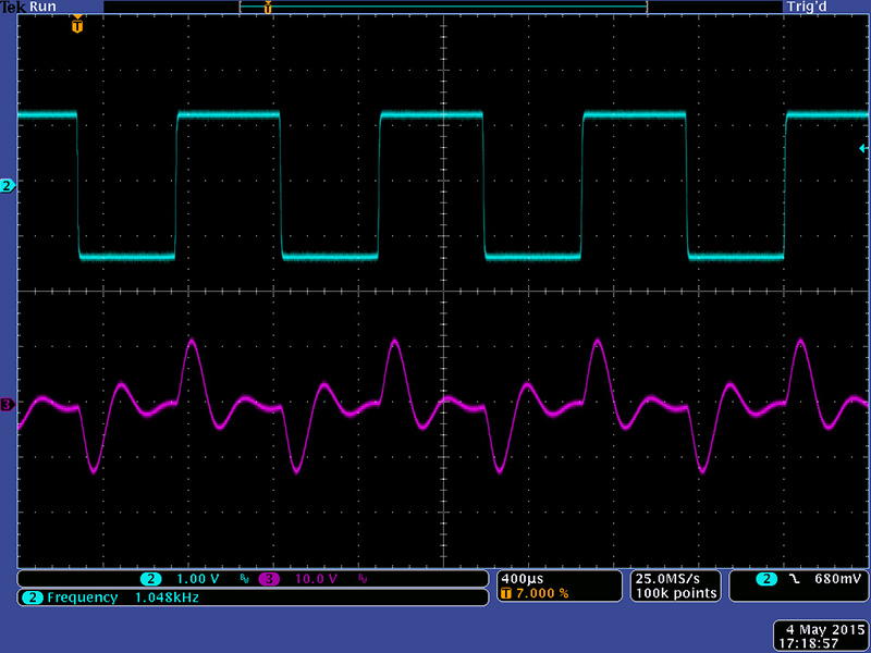
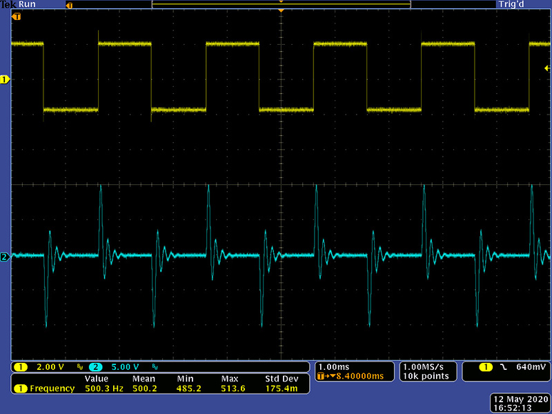
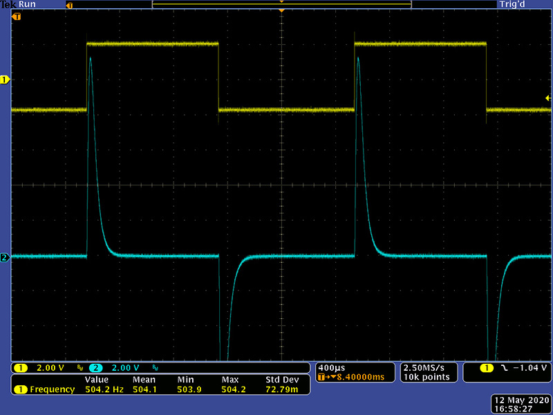
Adjusting the Q can further morph the output. I've adjusted the input level down more to eliminate clipping..

V2
I built a single board V2. I matched all 8 vactrols which measured 3K5 at 5 mA (that's just the value for 8 identical vactrols). When testing on the bench, I had my scope displaying the input signal and I noticed it didn't short out when I inserted the plug. On checking, not one of the 3.5mm "G" pads connect to anything!
I pulled the panel and wired all the top jacks and bottom jacks together and brought the ground wires out the lower output jack openings and soldered to the potentiometer ground pad.
Vactrols V3-V4 and V7-V8 are the input/output pairs. Vactrols V1-V2 and V5-V6 are the filter core pairs. JFETs Q1 and Q3 are the filter core input buffers and Q2 and Q4 are the filter core output buffers.
PCB Rear Reference Designators
The resulting filter is one of the nicest I have seen. I haven't experimented with different vactrol values but the 3K5 at 5 mA seemed to be a good value. The output is unity when set to low pass.
The output is unity when set to high pass.
These next two images show the impact of resonance. Note the scale for the output has increased to 5V/Div so the peaks are hotter but the sound level is good.
I experimented with the control settings to maximize the output to see how hot the signals got. These settings just about double the filter output level.
When set to high pass with resonance the peaks are nearly to the power supply rails but they are narrow and the sound is good. I chose to not make any adjustments to the filter gain.
Epilog
I have done repairs on various 291s where the output is too hot. I didn't measure the vactrols or JFETs but reduced the filter gain by decreasing R3 and R45 (R4 on the original schematics) from 33K. I've used values in the 7K5 to 15K. I sometimes also increase R1 and R43 (R6 on the original schematics) from 5K6 to 10K. An easier way would be to build them with larger value trimmers, increasing from 5K to 25K.
The Muffwiggler thread 291r rev2.0 PCB fault - info (dual buchla bandpass) has information about shorted traces on V2.0 PCBs with this text If you have a 291 and your lower Bandpass is pinned to a power rail... check under r52. The two sides of the vactrol are bridged by the highlighted trace that shouldn't be there and image. I have not seen this on any of the V2.0 builds I have done so I can only assume this is a bad lot of PCBs. This board was purchased march 2018. FYI.