 |
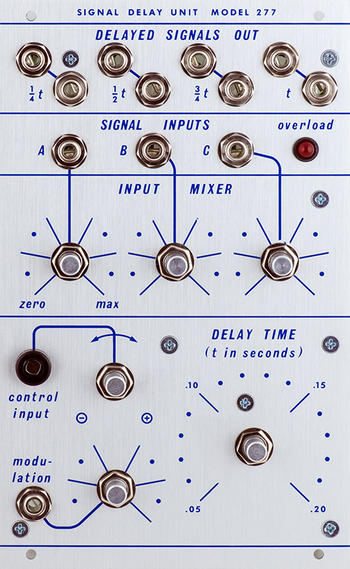
277 Signal Delay Unit |
|
A customer sent me a partially built 277 Signal Delay Unit and I finished assembly. Episode 13, as featured in the Muffwiggler Morton Subotnick Buchla Interview thread from the Source of Uncertainty podcast, features a review of the 277 which has many sound samples. Morton is worth a listen as well.
There is also YouTube video Source Of Uncertainty Episode 13: Signal Delay Unit Model 277r that features the patches.
I did bus the grounds between output pairs rather than running two separate grounds to each jack. The eeproms are not painted since I burned them as they didn't come with the PCB.
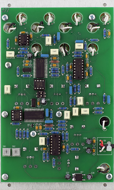
TR1 and TR2 will adjust the distortion but simply set them to center.
Operation
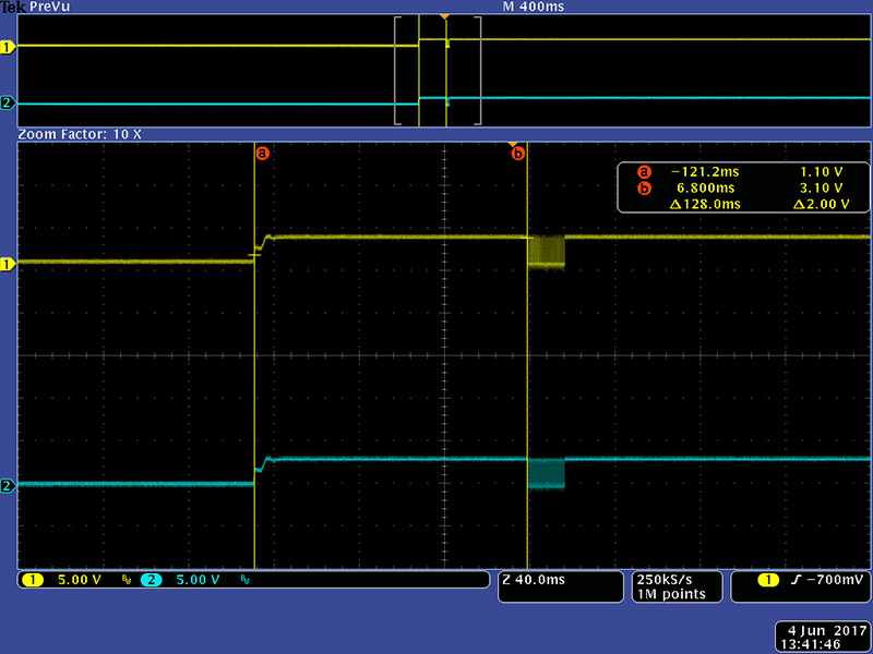
This image shows the power-on delay of 128 mS to start transferring the contents of the eeprom.
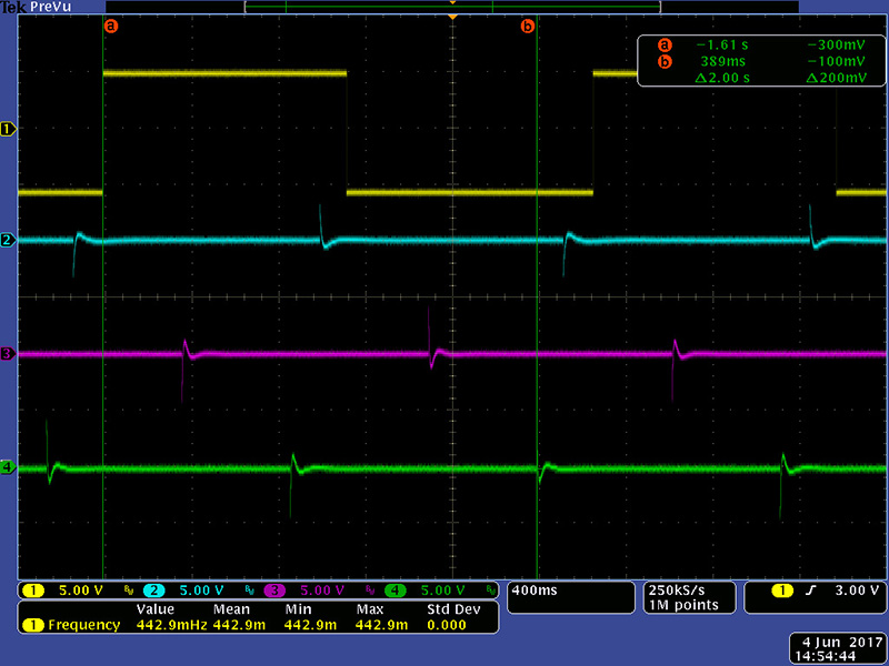
This image shows the input and the 1/2T, 3/4T, and 1T outputs.
This image shows the maximum delay of 2 seconds.
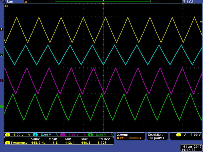
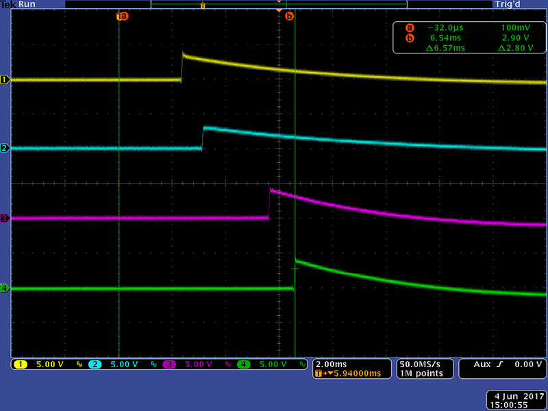
The minimum delay is a bit more complicated. There is processing time from the input to the output and then delay time between the outputs. The input rising edge is at the first cursor and all four outputs are shown. The delay from the input to the 1/4 output is 2.3 ms.
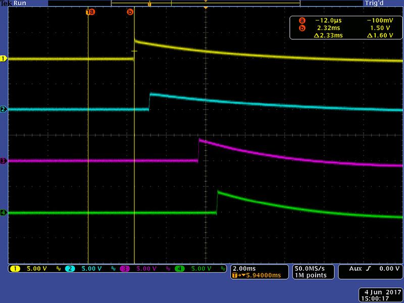
The delay from the 1/4T output to the 1/2T and from the 3/4T to 1T output is 929 uS. There is extra processing time of 1.4 mS from the input to the 1/4T output. This same delay can be seen from the 1/2T to 3/4T output when the second Spin FV-1 has to process the 1/2T input.
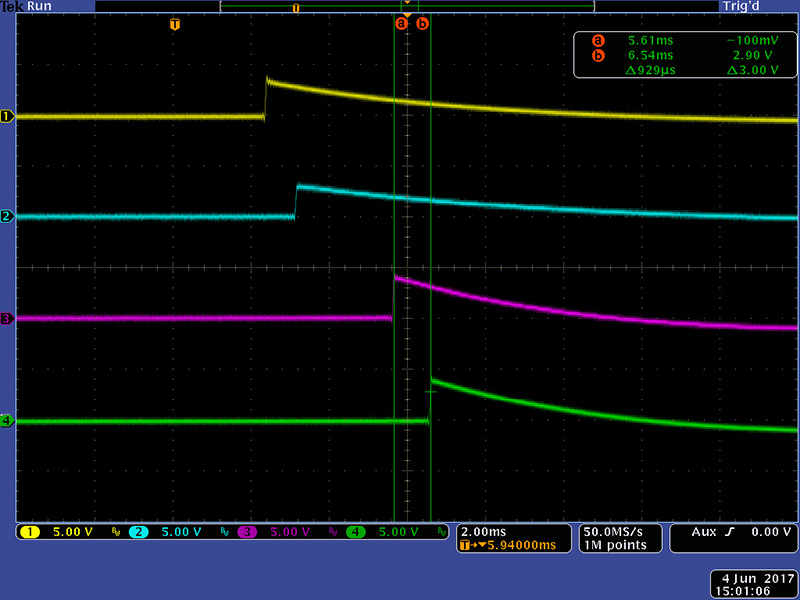
Thus the minimum delay is 6.5 mS but the delays between the four outputs are asymmetrical at 0.9mS, 2.3mS, 0.9mS.
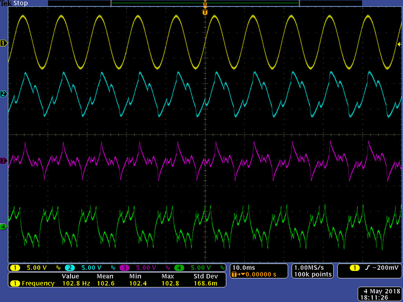
This scope image shows ~100 Hz sine wave FM modulated by a second oscillator running at close to the same frequency.
V2.0
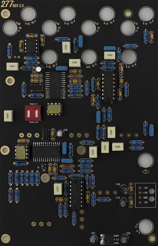
The V2.0 build is slightly different. Here are the main differences with the PCB.
The solder mask is black. There are no provisions for 9mm potentiometers. They all need to be 16mm right angle Alpha.
Trimmers TR1 and TR2 are removed. They are replaced by four 10K 1% resistors R51, R52, R53, and R54
The DIP switch is completely different. A Mouser 706-76RSC02T dual rocker switch will fit.
I did use the provided "painted" eeproms for this PCB.
Modifications (both V1 and V2)
Max Lord made a significant upgrade to the firmware which is described in the Modwiggler thread Do You Want Your 277r Signal Delay to Sound Good?
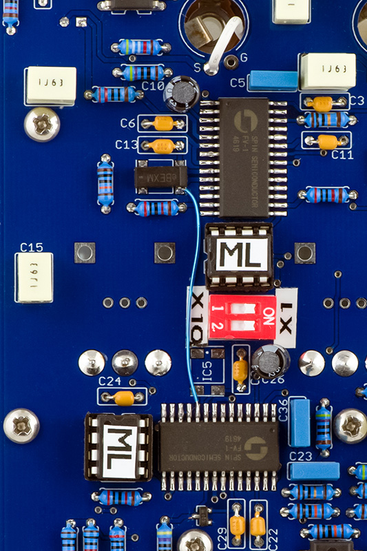
I also modified the module to use just one resonator to drive both Spin FV-1 ICs as Henrik mentioned in this same thread. Simply remove the bottom resonator and add this one wire. This is the Blomman version of the PCB but the modification is the same.
The FM input on this Spin FV-1 design drives the Rin pin. The signal is unbuffered, highly attenuated, and is reported as noisy. The FM effect candidly sounds bad. I've investigated increasing the amplitude of the signal, but just makes it sound more unpredictable and worse.
The FM input on the vintage/original 277 is just a capacitive coupled input to the CV with higher gain so audio signals can modulate the delay. I chose to modify mine in a similar fashion. I removed two resistors to eliminate the attenuation and break the path to the Rin pin. Adding a resistor connects the FM attenuator, through R43 and C35, to the input of the CV summing circuit. Remove R38 and R43. Wire a 47K to 51K resistor from the bottom pad of R38 over to the right pad of R50. Note the FM input adds to the CV input and Delay control, but the Schottky clamp diodes D2 provide over/under voltage protection for the Spin FV-1. I can now dial in a subtle vibrato to a significant modulation.