|
265 Source Of Uncertainty |
|
I did not build this 265 Source Of Uncertainty but repaired and modified it.
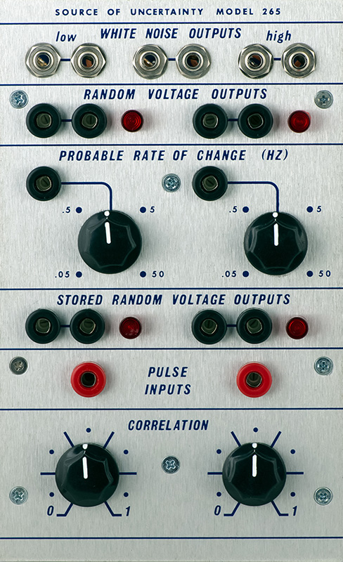
Operation
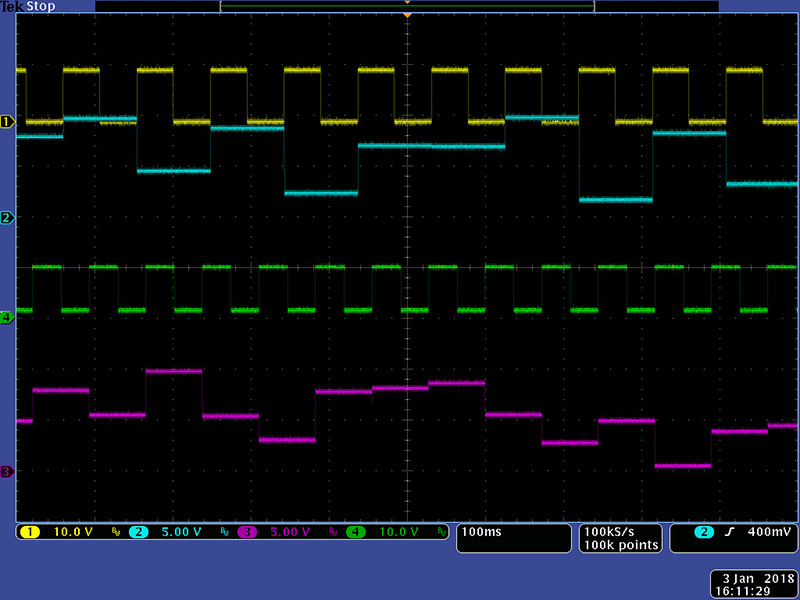
This scope image shows the Random Voltages with a mid probable rate of change.
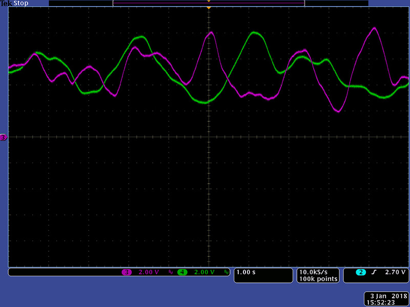
This scope image shows the Stored Random Voltages with a high correlation. The pulse threshold for the left input was 7.5V and the threshold for the right was 5V.
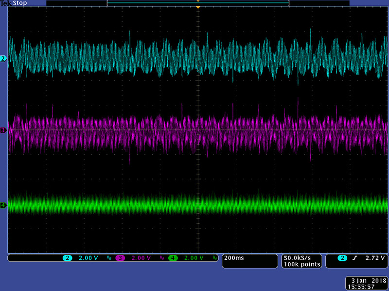
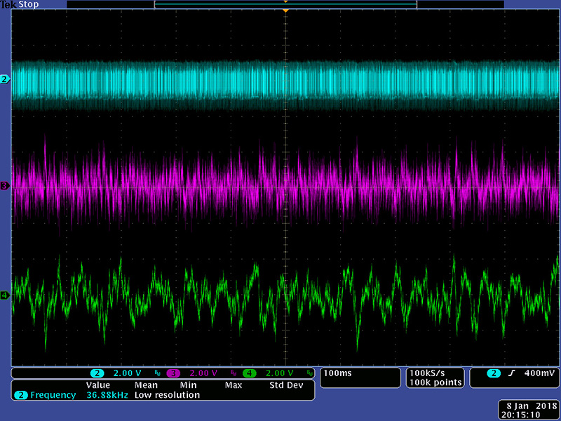
The noise source uses a zener diode followed by a high gain transistor and op-amp the same as the 212 Dodeca module. Similar to the Dodeca module the noise source isn't very good. It picks up hum and sometimes oscillates which is probably a combination of circuit design and PCB layout. You can see the hum "bars" in this scope image of the three noise outputs.
Modifications
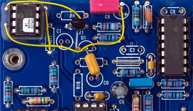
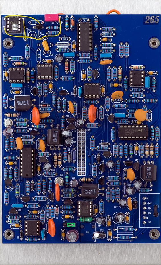
I found it easier to replace the original noise circuit with the Electric Druid Noise IC similar to my modifications for the 212 Dodeca module. I epoxied a 8 pin socket on top of some PCB insulating material in the upper left corner for the noise IC. I removed the parts associated with the zener diode and transistor amplifier and modified the circuit for the high noise output only. I added a 78L05 regulator since this board does not use +5V and didn't want to run an extra power wire. The yellow capacitor at a slight angle is a 1 uF capacitor on the output of the 78L05 regulator.
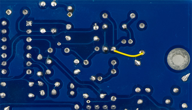
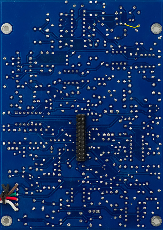
I just ran a single ground wire on the rear of PCB2.
The noise outputs sound much better.
265 Noise Modifications I wrote these after doing the mod so they are unconfirmed. Contact me if you did this modification to confirm it is correct.
The Electric Druid IC requires +5V. You can either run a separate power wire to the +5V or you can add a local regulator from +15V. I chose to add a local regulator.
I mounted a socket for the Electric Druid Noise IC. I used an 8 pin DIP socket and cut off pins 2, 4, 5, 6, and 7 and folded out pins 1, 3, and 8. I cut a piece of blank PCB material slightly larger than the socket and glued this with epoxy in the upper left corner as an insulator. Then I glued the socket with epoxy to the insulator.
|