 |
208 V2.1 Stored
Program |
|
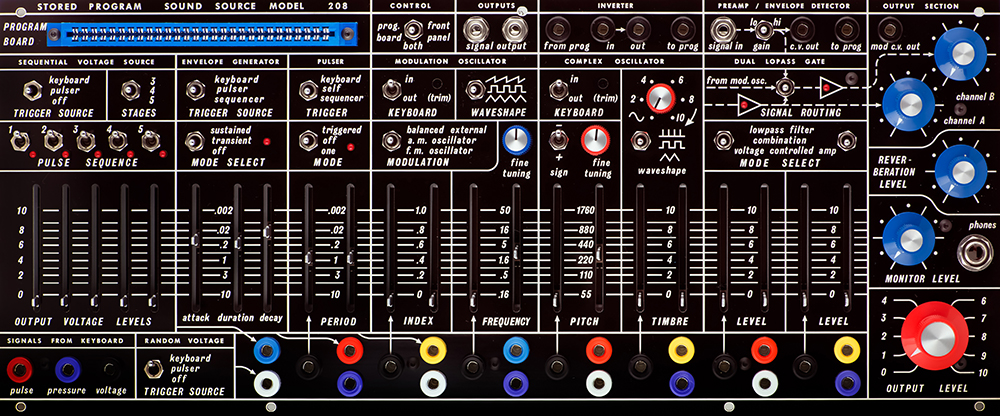
I built a V2.1 black 208 Stored Program Sound Source module for someone else. I ended up purchasing all of the parts for this module except the switch caps and knobs.
After assembly I did find a defective C&K 1P3T switch. I have seen several of these switches broken in repairs I have done. Check your 1P3T switches before assembly!
There is a panel mounting screw under the large red knob. This requires the red knob to be raised off the panel and you need more shaft so the set screw will mate. I did not put a backing nut on this potentiometer so the shaft would extend more through the panel.
The PCB panel definitely is less rigid than the aluminum panel. There is some flex to this module, but not much. You do notice it when inserting the cards in the rear.
The spacing for the shorting bars is not as good as the aluminum. There are several "pairs" where you can't insert the bar (or at least I didn't want to force it).
 |
I test fit the switches and potentiometers before I clear coated
the panel so I would keep handling to a minimum.
I used tac rags to clean my bench and the PCB and and then applied Krylon Crystal Clear Acrylic Coating 1303 in one coat. Even so, this acts as a dust magnet and there are a few areas with some minor dust. |
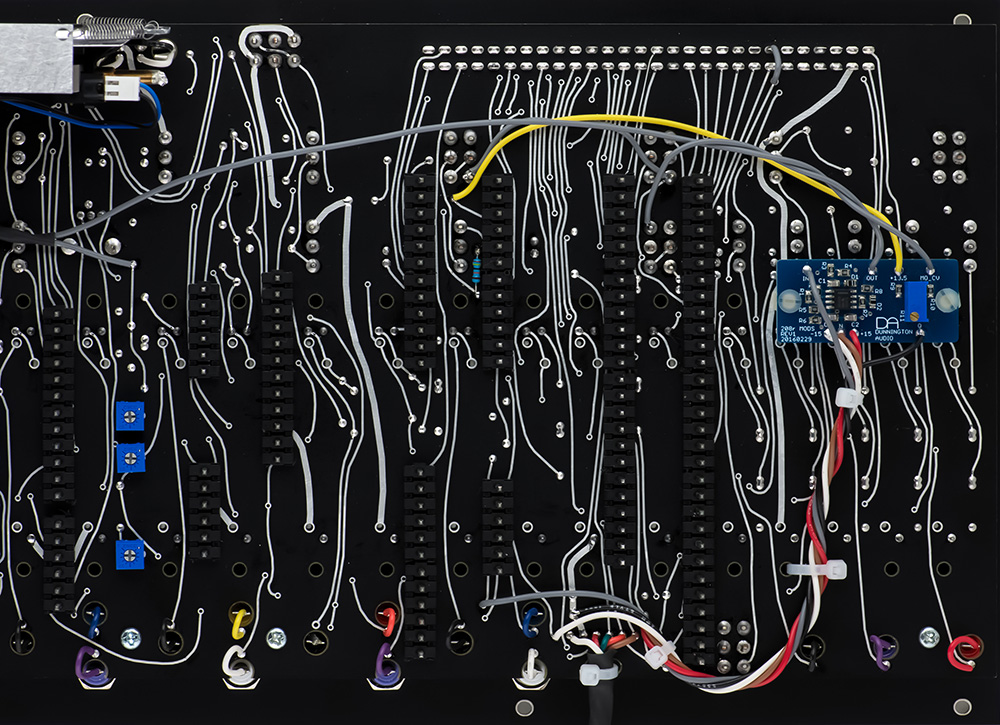
This 208 has both the Dunnington Mod Board and the Infinite Sustain Board added. You can also see two pieces of RG-174/U coax for the reverb return and the preamp input.
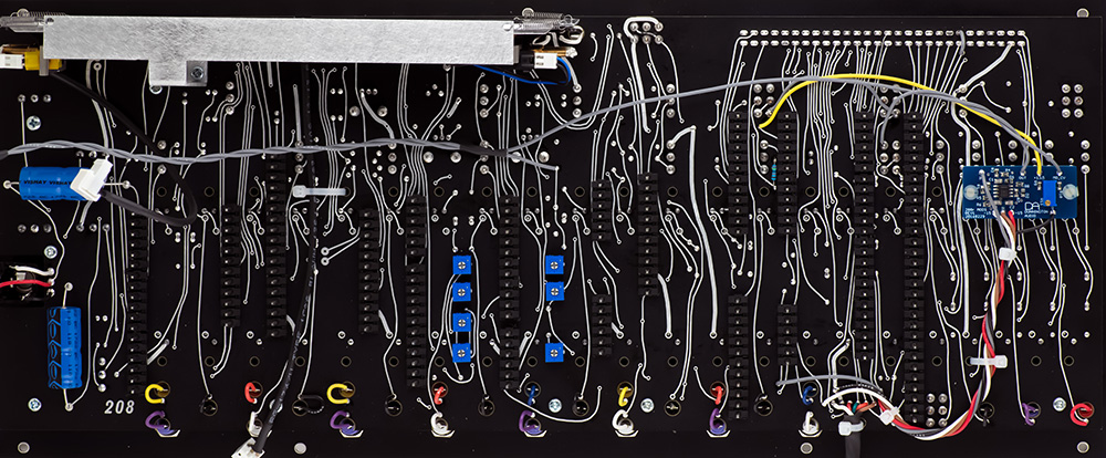
Dunnington Mod Board
I chose to make all the connections to the Dunnington Mod Board on the rear of the motherboard. The two gray wires connect to the MO octave switch off module.
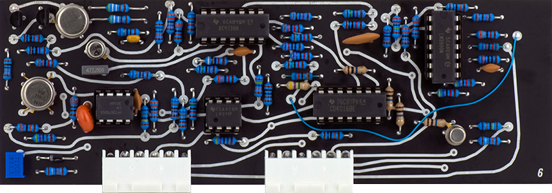
Cards
The black cards are quite nice looking so I decided to take photos of them. These took 14 hours to build.
Card 1 is the Sequencer.
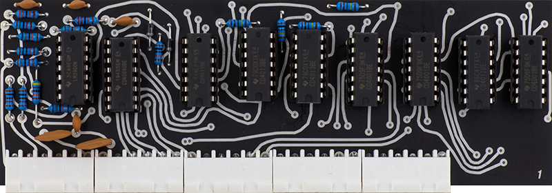
The back shows the decoupling capacitors that need to be added to this card.
Card 2 is the random voltage source and has one wire.
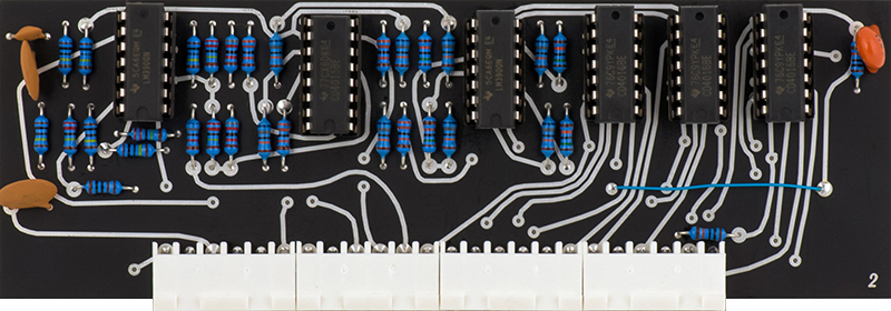
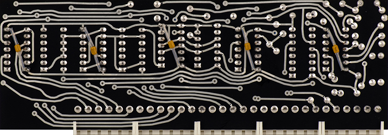
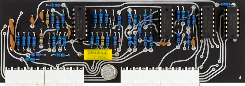
Card 3 is the envelope Generator and has two wires.
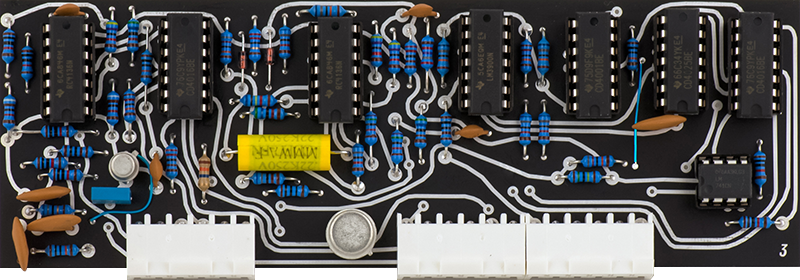
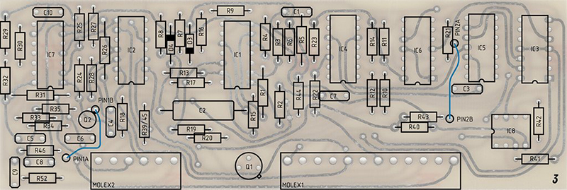
The reference diagram omits R52 in the lower left corner.
I've upgraded Card 3 with the Dunnington Audio Music Easel Infinite Sustain module.
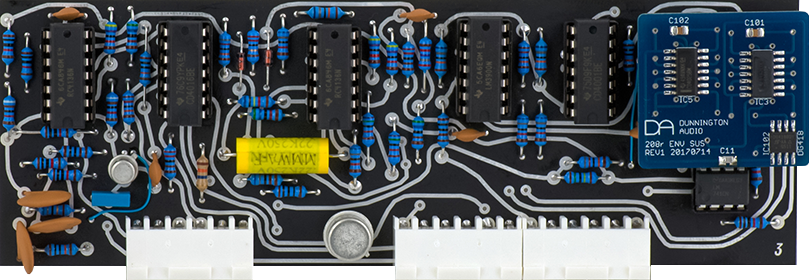
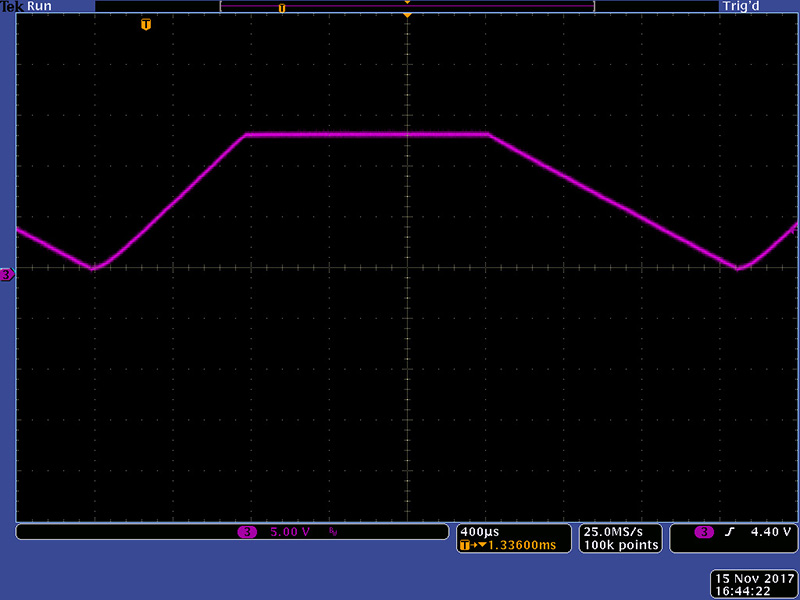
The envelope output showed signs of oscillation as can be seen in this scope image.
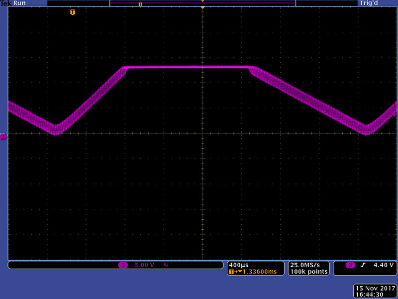
I added a 100 pF capacitor across Card 3 IC1 pins 12 and 14 to tame the oscillations.
Card 4 is the pulser.
Card 5 is the balanced modulator. I matched the pairs of vactrols on this card.

Card 6 is the modulation oscillator.
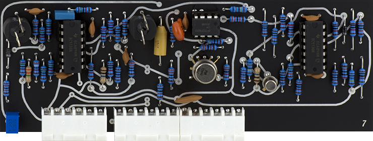
Card 7 is the first of three cards for the complex oscillator.
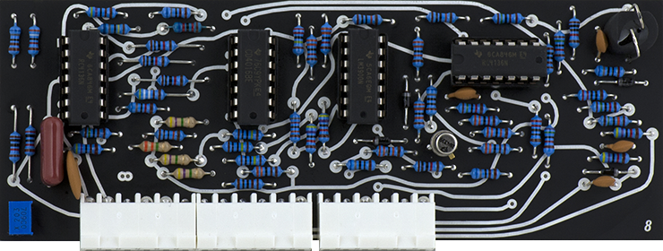
Card 8 is the second of three cards for the complex oscillator. TR3 on the motherboard connects to pin 11 of card 8, not pin 12 so a modification on the motherboard is needed.
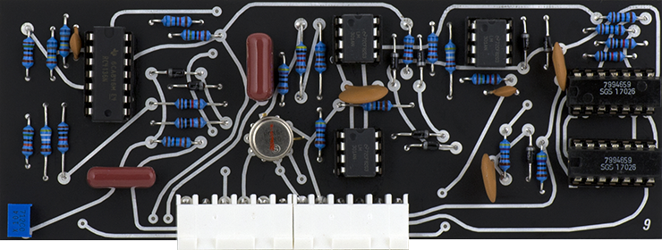
Card 9 is the third of three cards for the complex oscillator.
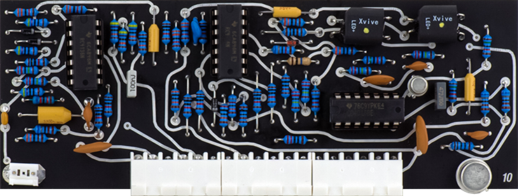
Card 10 is gate 1 and the preamp.
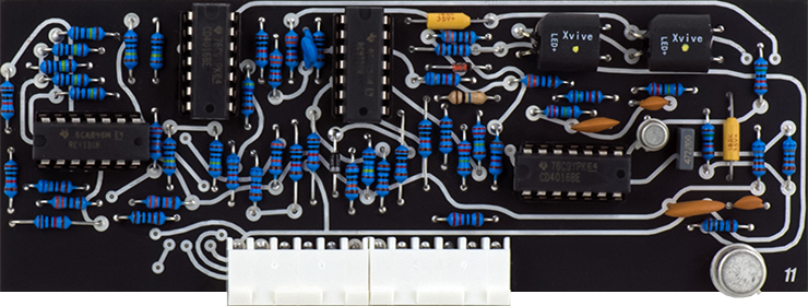
Card 11 is gate 2.
Card 12 is the reverb driver and output. The reverb on these is pretty muddy. I cut the trace on Card 12 to edge pin 12 and added a 15K resistor. This keeps some dry signal present when the reverb control is turned fully CW.
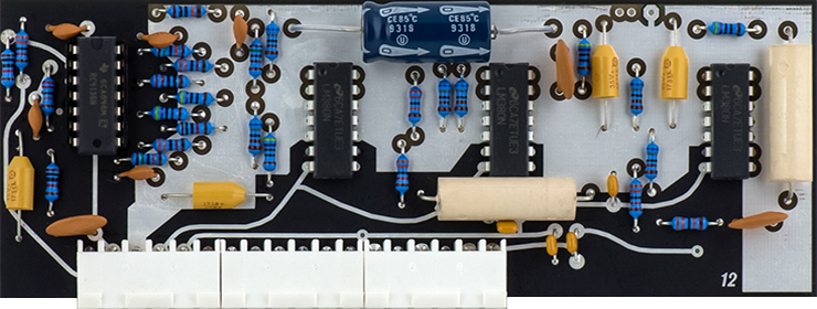
The reverb circuitry on Card 12 is pretty poor. You can upgrade it with the Boops Card12 Replacement.
Modifications
These are the modifications changes between V2.0 and V2.1
Corrected:
Missing trace on motherboard between SW1 and SW8
Missing trace on motherboard between Molex 4A and Molex 3B
Card 2 trace to R31
Card 3 pinout of Q2 and addition of 100K resistor
Not Corrected:
Missing trace on motherboard between Program Card pin 7 and via
Motherboard trace to Card 8 pin 11 instead of pin 12
New The tab closest to the pins on the MO and CO fine potentiometer can short to the -15V run underneath. This tab is connected to the shaft and on a V2.0 can short to the panel. Since the V2.1 panel is a non-conductive PCB, there is no short to any other circuit. However, I would recommend you break this tab off before soldering. If your V2.1 is already built, then you can desolder these controls from the rear, and pull them off the board. I raise them until the pins are flush with the PCB and then resolder.
Additional Modifications
To improve the sequencer reliability, solder 0.1 µF decoupling capacitors across the power pins on at least half of the ICs.
To improve timbre performance, Card 7 R3 should be 10K, not 1K8.
To improve the reverb performance cut the run on Card 12 to IC1 pin 5 and run a coax cable directly from the reverb output to IC5 pin 1. Ground is on a nearby trace. You can also cut the run on Card 12 to edge pin 12 and add a 15K in series.
To improve the AM index do the modifications on Card 5 to set the wet and dry levels as described on the V2.0 page.
To improve MO audio mix at low frequencies, increase C4 on card 11 to 47 µF.
To improve trigger performance with a 218, parallel a 240K resistor across R56 on the back of the motherboard to change the pulse in threshold from 10V to 5V. This changes the threshold for the Pulser, Sequencer, and Envelope Generator.
Add a 100 pF capacitor on Card 3 IC1 pins 12 and 14 if there are oscillations in the EG output.
On some units I have seen the EG output with small high frequency oscillations. Adding a 100 pF capacitor across Card 3 IC1 pins 12 and 14 tames these oscillations.
To diminish bleed of the EG into the audio cut the run to the edge pin 5 on Card3 and solder a 1K resistor across the cut. Also add 0.1µF decoupling capacitors on the power supply pins on IC1, IC4, IC5, and IC6.
To diminish bleed of the pulser into the audio cut the run to the edge pin 8 on Card4 and solder a 1K resistor across the cut.
The modifications for 1V/Oct or 1.2V/Oct are the same as for V2.0.
Calibration
V2.1 calibrates the same as V2.0