 |
207 Mixer/Preamp |
|
I built a 207 V2.1 Mixer/Preamp module for someone else. They sent me a mostly complete kit of parts and I assembled and tested the module. Many of the components are sourced through Mouser but specialized parts, panel, and knobs have specific sourcing requirements.
There isn't a lot of information or specifications on the 207. This documentation comes from the November 16, 1981 Buchla Synthesizer User Guide by Daniel Scheidt.
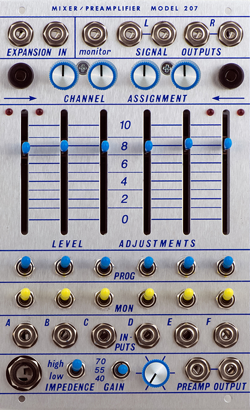
The preamp phone jack is a TRS. In the up position it functions as a TS unbalanced input with an impedance of roughly 1M. In the down position it functions as a TRS balanced input depending on the specific transformer. The original transformer had a turns ratio of 1:14.1 and an impedance ratio of 1:200 for an input impedance of ~5K. I am using a Sennheiser TM003 transformer which has a center-tapped secondary for a turns ratio of 1:15 which is very close to the original or 1:30.
The mixer input impedance varies with the settings of the sliders and balance controls between ~40K and ~13K. The external input impedance is higher at ~120K.
In addition, a high impedance monitor out signal is also sent to an MTS wire as part of the power cable. This can be connected to the MTS input on the 227 mixer.
Construction
These V2.1 PCBs are black solder masked. V2.1 BOM calls out 10 -100K for the 9mm potentiometers but they should all be 25K linear so the balance circuit works correctly. The original sliders were log instead of linear which I prefer better.
PCB V2.0 added six 5K SMT resistors from the wiper of the slider potentiometers to ground. This gives the linear sliders a strong log contour but also drops the input impedance down to around 4K. I believe the mixer works better without these resistors installed.
R74 is a 2K2 although the BOM calls out a 2K4. Either will work.
The transformer wires are identified by color. Green and gray are the input primary and red and blue are the output secondary of the transformer. The TRS input is labeled hot and cold with hot connecting to T and cold connecting to R.
There are also other minor errors on the BOM so I made some corrections. I also made reference diagrams from the PCBs.
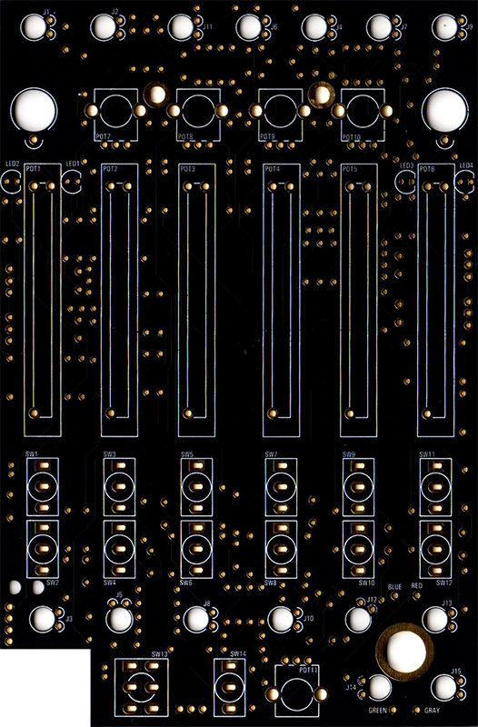
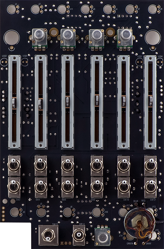
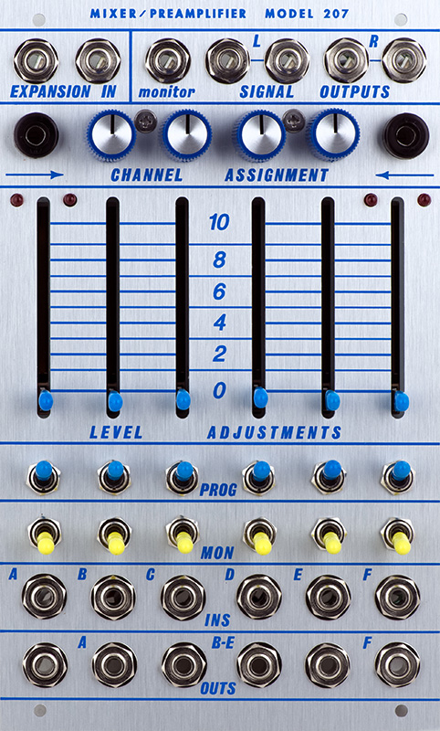
207 V2.1 Front Reference Diagram
207 V2.1 Front Reference Diagram
Transistors Q1-Q2 and Q3- Q4 should be matched. I did my transistor matching with a Tektronix 576 Curve Tracer although cut-tape 2N3904s would work well.
![]()
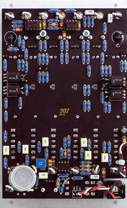
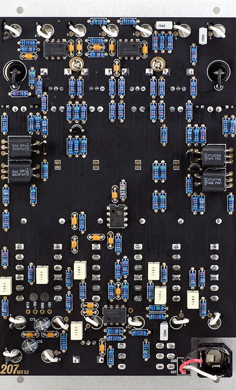
The Sennheiser TM003 transformer mounted nicely on the PCB with various washers. There isn't much room for the transformer wires so they have to be pressed close to the PCB. The black wire to the right is a ground wire for the transformer shell.
Rotating the four jacks surrounding the transformer wires with the tip connector oriented away provides the maximum space for the wires..
This is one of the more difficult panels to install. The holes for the wires are small, the transformer covers some of the holes, and the transformer wires interfere with the jacks. I added a plastic washer between the transformer and PCB since the metal can is close to pads. I ran a ground wire over to the hole pad so the transformer shell would be grounded. Since I didn't know the transformer wiring I verified correct phase with a test signal to make sure the output was in phase.
I did not install the SMT resistors to keep the input impedance as high as possible.
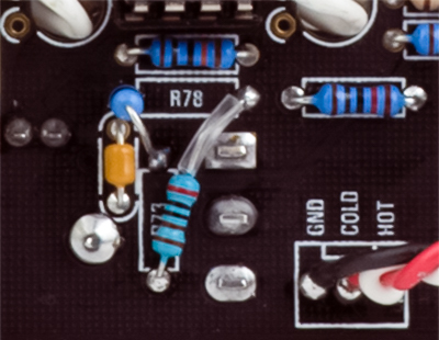
Although the preamp gain switch operated and provided three different gains, it didn't match the front panel. R73 and R78 are not wired correctly. I simply installed these two resistors as shown to match the front panel legends. R78 mounts radially and R73 gets wired across to the end pad of R78.
Calibration
There is only one trimmer, TR1, which is adjusted by measuring the output on IC3 pin 1 and adjusting for 0.0V on the highest gain setting.
Channels A and F have different gains from channels B - E because of variations in the vactrols. I hand selected R3, R9, R46, and R50 to match the gain of the other channels. R3 adjusts the left gain and R9 adjusts the right gain of channel A. R46 adjusts the left gain and R50 adjusts the right gain of channel F.
V1.1
V1.1 appears to be the same as V2.0 with a few minor exceptions. The six 5K SMT resistors are not present, there are two 10R series resistors in in series with the +/-15V supplies, and the bulk electrolytic capacitors are larger at 100 µF. All of the reference numbers are different but the layout is very similar with the exception of the MTS pad is at the top of the board. BOM V2.0 is used with this PCB. The four resistors for setting the gain of channels A and F are R18, R20, R55, and R59.
V2.0
V2.0 appears to be very similar to V2.1 with the exception that almost all the reference numbers are different. The gain switch is wired with minimum gain in the up position and maximum gain in the down position. To correct cut the runs on the front of the board to the top and bottom switch pad and reverse them with jumpers. There are also some minor spacing issues such as insufficient clearance around the two standoff holes so an insulated washer is needed under the screw. The GND connection to the plane also is very narrow. The four resistors for setting the gain of channels A and F are R18, R20, R55, and R59.
V3
V3 appears to be the same as V2.1 with the change from a transformer to an active circuit for the microphone preamplifier. However, the six 5K SMT resistors are now listed as 0.1 µF capacitors in the BOM!
![]()
This is an obvious error as they are from the slider wiper to ground and form a low pass filter. Again, I would recommend no SMT parts be installed.
This is a 207 V3 I built for myself. I have not yet done the modifications to balance channels 1 and 6 and reduce the LED current.
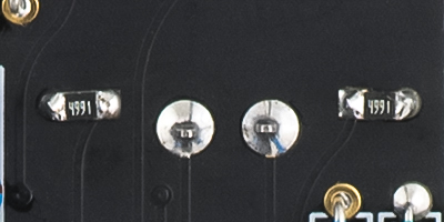
The minimum current through the vactrols was enough to illuminate the off LED. I added 10K resistors across the LEDs to divert some of the current on another module but found I needed to drop them to 4K99 on this module. I used 0805 SMT resistors which fit nicely between the pads.
Custom 207 Build
I was asked to modify a 207 with a custom panel to provide separate outputs for A, B-E, and F. The preamplifier section at the bottom has been replaced with 6 output jacks. The A channel left and right output jacks on the bottom left and the F channel left and right output jacks are on the bottom right. The B-E left and right output jacks are on the bottom middle.
I chose to use a V2.0 PCB since I wanted to cut the bottom of the PCB off to better access the jacks. I used shielded wire for the 6 separate inputs.
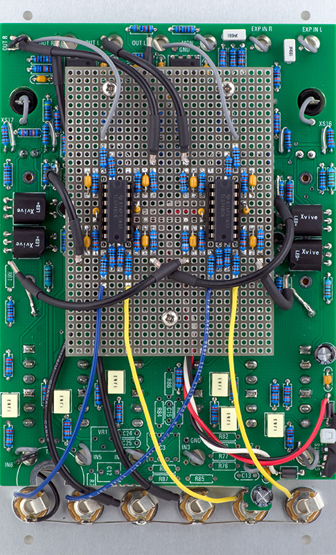
As typical with this module I modified R18, R20, R55 and R59 to provide unity gain in channels A and F so they match B-E.
The minimum current through the vactrols was enough to illuminate the off LED. I added 10K resistors in parallel to all the LEDs to divert some of the current so at either CV extreme one LED was off.