|
204 Quad Spatial Director Module |
|
I was sent a 204 Quad Spatial Director module to repair.
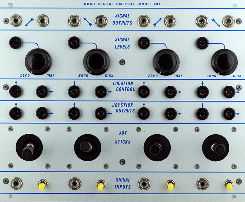
The 204 Quad Spatial Director is a voltage controlled quadraphonic mixer for determining the spatial location of sounds with two CVs. It consists of four 2 axis joysticks with individual 0 to 10 volt CV outputs. The joysticks can be used to control the sound location if patched with shorting plugs to the Location Controls or they can be used for any other CV function.
The four output pairs are indicated with arrows for front left, rear left, rear right , and front right. Each output has a VCA with a level control and CV input. When the two Location Control CV inputs are patched to the joystick CV outputs the joystick maps the signal input to the appropriate output. The four switches also route the input signal to a MTS output on the PCB for monitoring purposes.
Construction
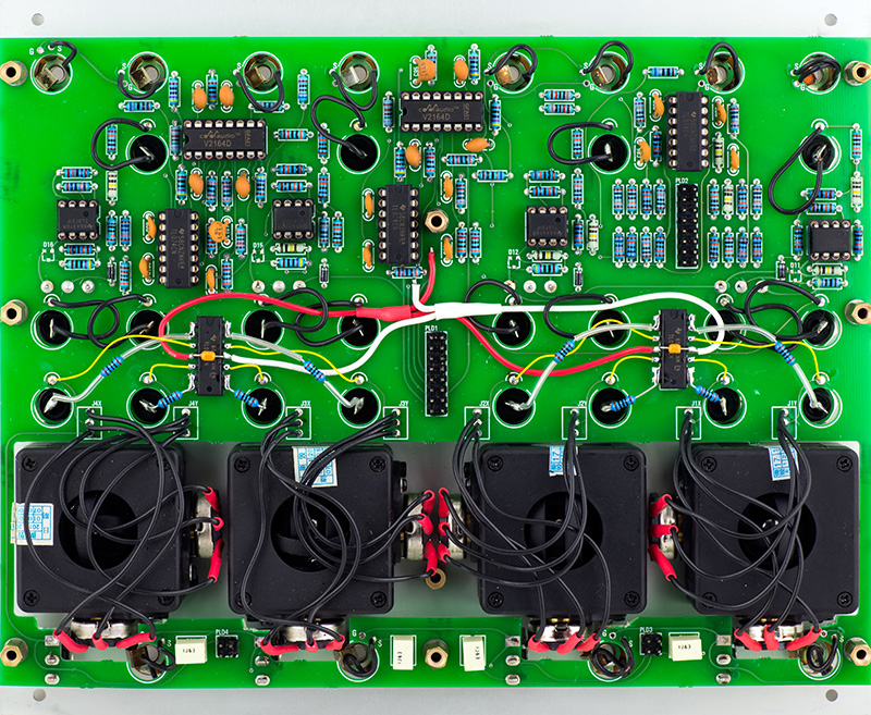
The module consists of two PCBs. The rear PCB contains the panning circuitry. An ATTINY84 with a MAX534 quad DAC converts the two CV inputs into four panning CVs with 2164s as conventional VCAs for each channel . All of the BAT54S protection diodes were missing on this PCB (see below).
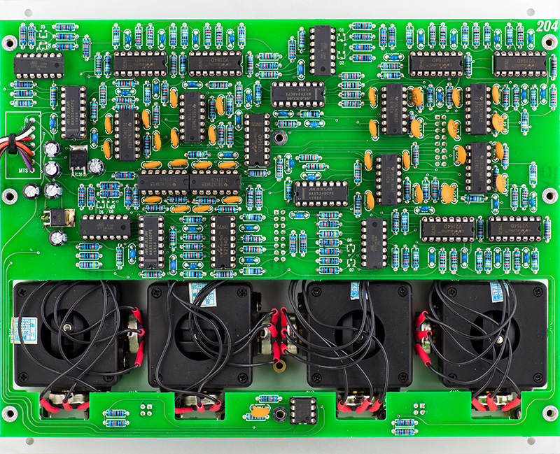
The front PCB contains the voltage regulators and joysticks along with 2164s configured as four VCAs for the output circuitry. All of the BAT54S protection diodes were missing on this PCB also. Mouser no longer stocks the BAT54S but they do carry the BAT54SFILMY (Mouser 511-BAT54SFILMY) which I added after the photo was taken.
This unit had two burned out joysticks. The joysticks are powered from +10V and the wiper goes directly to the output jack. As such it is not short circuit protected and shorting an joystick output to ground will burn out the potentiometer depending upon its position. You can see the burned track and the wiper in this photo.
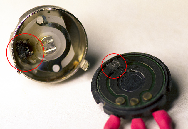
The BOM specifies an eBay item number for the joystick which is only available in the UK. They appear to be 100K. I could find similar joysticks in China but they were 10K (item #122831118333). Since they are just attenuators the value doesn't matter except for the output impedance. I wanted to add some short circuit protection which could simply be a series resistor between the wiper and the output jack but I didn't know the wattage of the potentiometers. Assuming 1/8 W, a 500R series resistor would suffice. Since I had a mix of 10K and 100K potentiometers I decided to buffer the joysticks to have a uniform output impedance. I attached two TL074s to the PCB with foam tape and added 100R series resistors to the outputs. +/-15V can be found on two vias above the middle connector. No more burned out joysticks!