 |
DJB-MIDI Processor Project |
|
This page describes my latest DIY project. I ported my AVR code to an ATTINY2313 to use as a MIDI processor. This circuit is low enough power to operate from the MIDI-In connector. The twelve DIP switches select the following functions:
SD5 Note transpose on/off
SD4 Channel transpose on/off
SD3 Note reverse on/off
SD2 Multi keyboard on/off
SB7 Note transpose bit3 0/1
0-11 transpose up 0 to 11 semitones
SB6 Note transpose bit2 0/1
12 transpose up 1 octave
SB5 Note transpose bit1 0/1
13 transpose up 2 octaves
SB4 Note transpose bit0 0/1
14 transpose down 1 octave
15 transpose down 2 octaves
SB3 Channel transpose bit3 0/1
0-15 selects MIDI
channel
SB2 Channel transpose bit2 0/1
SB1 Channel transpose bit1 0/1
SB0 Channel transpose bit0 0/1
Note transpose adjusts all MIDI note on and off
commands by 0 to 11 semitones or +1, +2, -1 or -2 octaves as selected by SB7 - SB4.
Channel transpose replaces the channel in all MIDI commands with the channel selected by SB3 - SB0.
Note reverse inverts the keyboard around key C4. D4 is transposed to A3#, etc. Note transpose operates after the reverse function.
Multi keyboard splits and replicates the keyboard at key C4. The notes below key C4 are scaled up two octaves and the notes at key C4 and above are scaled down 2 octaves resulting in two keyboards with key C2 and key C6 playing C4 (middle C). Positioning your hands appropriately can 'reverse' the registers with your right hand playing the low notes and your left hand playing the high notes. Add reverse for an even crazier mode as each multi keyboard reverses. Note transpose operates after the multi and reverse functions
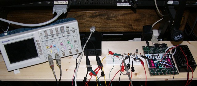
Below is a photo of the functional prototype.
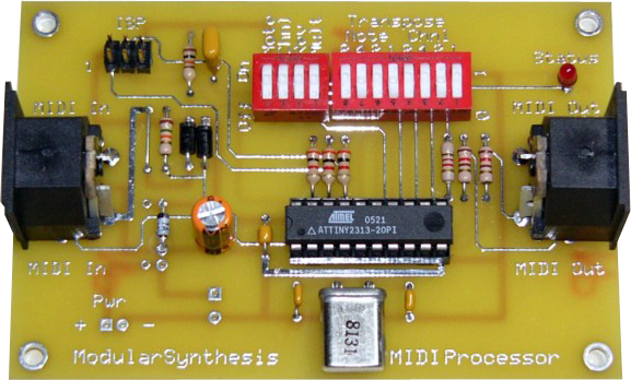
Here is the pcb layout I designed using the ExpressPCB mini service. I later changed the two black schottky diodes to 1N4148 diodes and removed the gray zener diode. The regulation varied slightly so I decided to use the crystal oscillator to ensure accurate serial data timing. With the crystal oscillator I can let the voltage vary slightly. It typically varies between 3.75 and 4 volts. The square pins, three series resistors, and the reset circuit are required for in-system programming and could be omitted. The unstuffed components are for optional external power and regulation. The status led blinks briefly on each MIDI command received.
DJB-MIDI processor source code