|
PAiA 2720 Synthesizer Restoration |
|
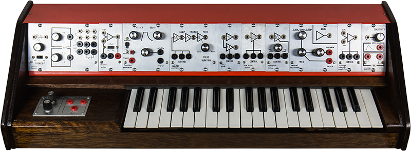
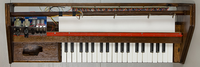
I obtained a PAiA 2720/R Synthesizer from a co-worker's estate and restored it. I remember when these came out but my interests had shifted to microprocessors and personal computing in the mid-1970's. Here is the ad from the 1976 catalog.

The restoration came out well. Someone posted a PAiA 2720 Synthesizer Restoration Blog topic on the PAiA forum and I started the topic PAiA 2720/R Restoration on the Muffwiggler forum and PAiA 2720/R Restoration on the Electro-Music forum. I strived to keep the synthesizer as original as possible. Most issues were electro-mechanical in nature which is pretty typical. This is a summary of the work I did:
| Cleaned everything |
| Refinished cabinet and added feet |
| Rebuilt mounting brace and added insulation over keybed |
| Tapped sheet metal for 6-32 screws and replaced most hardware |
| Rebuilt keyboard with new bushings and adjusted key alignment |
| Removed internal blocks and mounted keyboard to bottom panel |
| Resoldered and cleaned every PCB |
| Cleaned all potentiometers, switches, and jacks |
| Reformed or replaced 3.5mm jacks |
| Increased filter capacitors in power supply |
| Rewired and insulated mains circuits |
| Replaced all module power wires with common color code |
| Rebuilt glide PCB with new panel |
| Modified VCA for full cutoff (adjust R13 for no output a 0V control) |
| Moved low key potentiometer to original position on rear panel |
| Resoldered power supply bus with silver solder |
| Replaced few 748 op-amps and various off-value resistors |
| Added zero intercept to VCO |
| Added ~3X adjustable gain circuit for VCO triangle output |
| Replaced leaky blocking electrolytic capacitors with film capacitors |
| Calibrated keyboard and all modules |
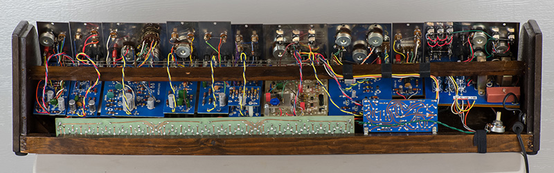
The synthesizer is now much cleaner inside. I calibrated each module with a bench supply and did a final calibration when reassembled with the PAiA power supply. The calibration was straightforward.
The remainder of this page is organized in the order in which I restored the synthesizer.
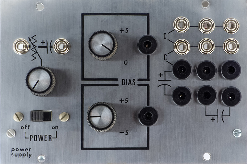
2720-7 Power Supply
The keyboard needed to be rebuilt so everything has to come apart to remove it. While I was working on restoring the cabinet I decided to rebuild the modules starting with the power supply. I want to keep this as original as possible but I wanted to clean up the mains wiring and insulate it as best I could. The 3.5mm jacks were highly corroded so I decided to replace them. I was not able to find a 2720-7 Power Supply User Manual so made a single page document from the Radio-Electronics article.
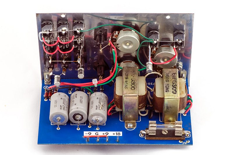
I resoldered most of the wiring and cleaned the panel and PCB. The 3.5mm jacks were quite bad so I replaced them all.
I noticed in this photo I haven't wired the NC between the two rows of 3.5mm jacks. Oops. Later I increased the filter capacitors.
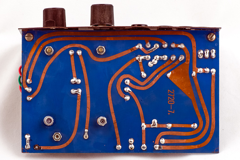
I noticed how close the top trace is to the panel and would short to the mounting rail. I finally figured out the L brackets are longer on one side than the other to allow clearance between the PCB and the panel. About half the modules were assembled wrong with no clearance.
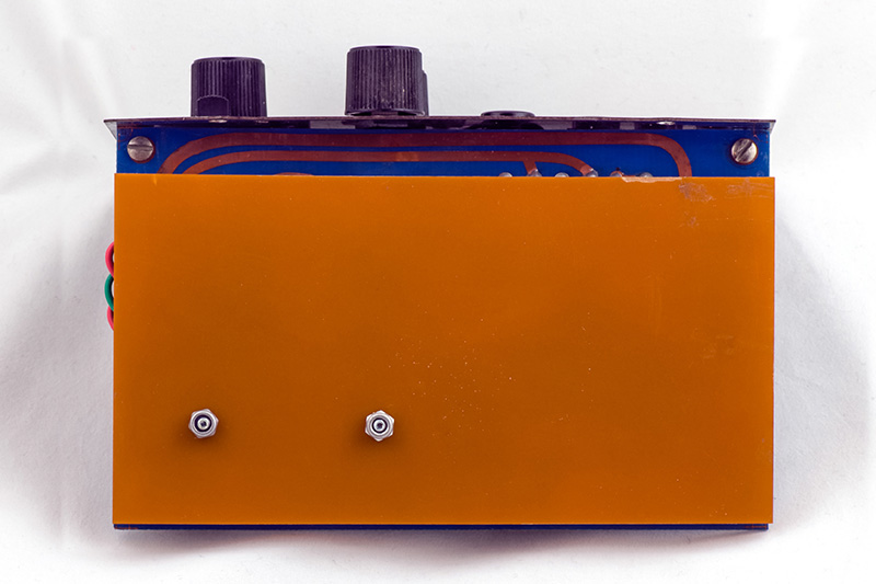
I added an insulating sheet over the exposed mains wiring and mounted it with two longer transformer screws. The rear of the PCB is accessible through the open bottom so I wanted to insulate all mains wiring.
There is a lot of ripple in the unregulated power supply so I increased the filter capacitors from 1000 µf to 2x 3300 µF (two stacked in parallel). I also made a fishpaper cover for the fuse holder.
Keyboard
The keyboard bushing were rotten so the keys stuck in the up position and some springs were missing. I bought new bushings from Syntaur and cleaned, lubed, and restored the keyboard.
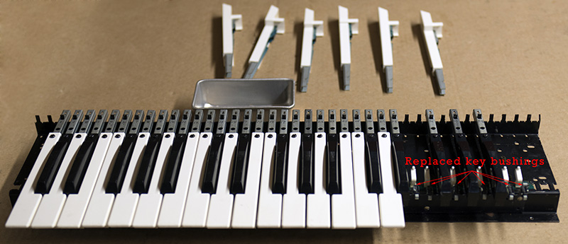
The keyboard case was built crooked so I sanded and shaped everything flat, remounted the bottom rear brace, and refinished the cabinet. Inside were two blocks to locate the keyboard in the cabinet but some keys would bottom out on the blocks. I removed them and drilled and tapped the keyboard front rail and mounted it with four mounting screws.
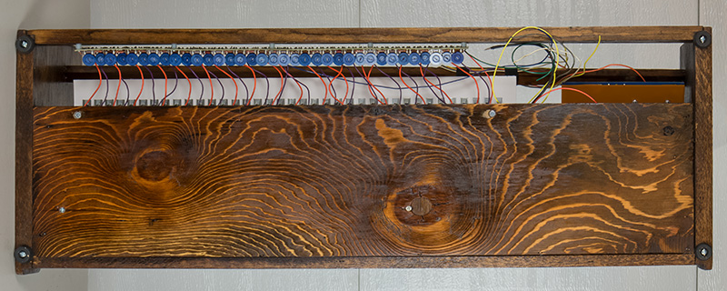
The bottom rail brace is mounted on two standoffs which is not very firm. I measured carefully and made a template of where the brace should fit and then made some mahogany spacers to the left and right cheek blocks. The left cheek block is not level so I had to taper the spacer. I stapled insulating paper on the bottom of the rail and covered it with 1/2" adhesive backed foam to fit tight against the keys.
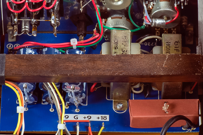
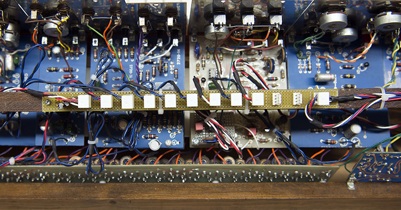
This image shows the insulation paper which protects the bottom of the PCBs from shorting to the keybed as there is little clearance. I also drilled a third hole to mount the bottom rail to the right side of the left cheek block to make it more stable.
All of the holes in the rails were stripped. I tapped them for 6-32 machine screws instead of 4-40 self-tapping screws. I rebuilt the power bus. It is made of piano wire which doesn't solder very well with standard solder. I used silver solder at 800°F which worked much better. The keyboard is now centered and the keys are even.

The keyboard S&H would benefit from a modern JFET op-amp but I decided to keep it original. The CV drops slightly when the key is release and then holds steady about 15 seconds and then quickly drops. I can always upgrade it but I like to keep vintage synths original as much as possible.
2720-9 Glide
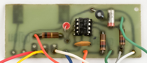
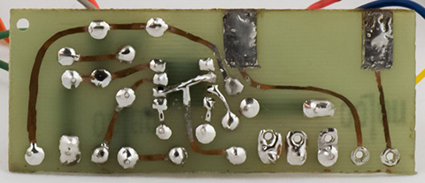
The 2720-9 Glide retrofit was a home-made PCB and panel. The PCB holes were oversize and didn't line up very well with the IC. I cleaned the soldering up and added wiring on the traces that were over-etched.
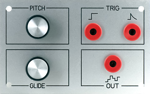
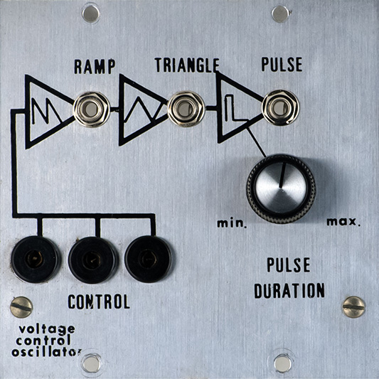
The panel was just a piece of aluminum cut crooked and unmarked. I designed a FrontPanelExpress panel similar to the original but with narrow outlines since they are engraved.
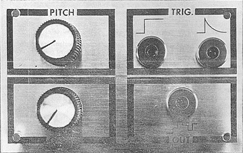
This is what the original glide panel looked like.
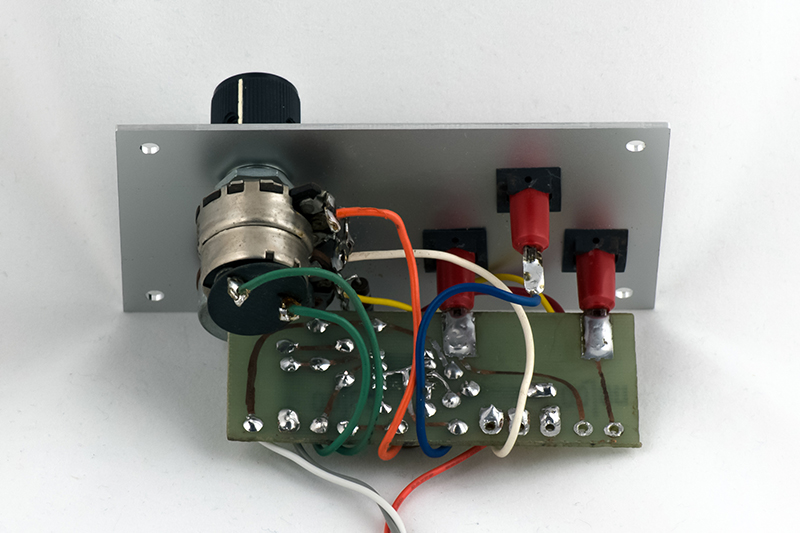
The rebuilt glide assembly ready for installation in the keyboard case. Later I would find that the 748 op-amp was a bit funny.
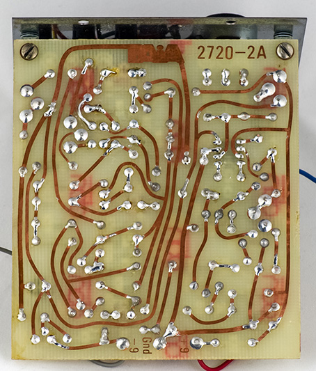
2720-2A VCO
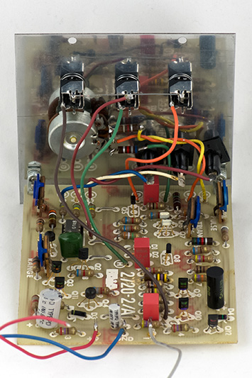
I resoldered the PCB and pressed the components flat to the board and washed it. This VCO had the balance trimmer modification with fixed resistors so I replaced them with a trimmer. The pulse width potentiometer had fixed resistors in series with each end but they worked well so I left them. I could not trim the triangle waveform at all and needed to increase R14.
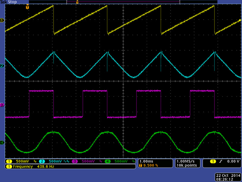
The pulse and ramp waveforms are nearly 1V pk-pk but the triangle was only about 0.320V pk-pk. The assembly manual says to verify all three waveforms are about 0.5V pk-pk but I left them at the higher amplitude (there is no adjustment anyways) and added an op-amp to scale the triangle to the same level. The DC blocking capacitors were all leaky so I replaced them with film capacitors.
I found that scaling the VCO by 1V would increase the frequency about 2.1X, or +5% which is at the top end of the specification. I thought about tweaking the circuit to get closer to 2X but decided against it. All of the resistors are 5% and I would end up replacing quite a bit of the circuit. I decided to leave it stock since the keyboard tuning will compensate.
My initial tuning of the keyboard circuit was aggrivating as I could not get the lower end of the keyboard in tune. I discovered that my glide module was adding gain. 5.0V CV from the keyboard increased to 5.3V through the glide module. Replacing the 748 op-amp fixed it and I was able to tune both ends of the keyboard. I adjusted the other two C keys and the rest of the keyboard was reasonably in tune so I left it for a final calibration when everything is complete.
This image shows the ramp, triangle, and pulse outputs from the 2720-2A VCO and the sine output from the 2720-14 Sine/PWM.
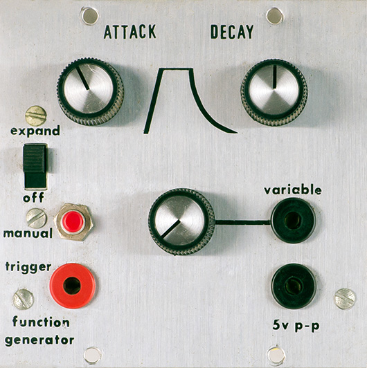
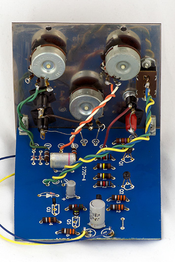
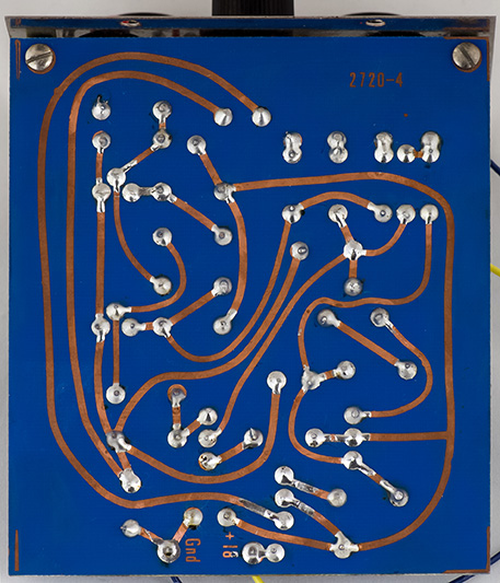
2720-4 Function Generator
The Function Generator is simply an AR module. It was reasonably well built and did operate. I simply cleaned all the switches and controls and cleaned the PCB.
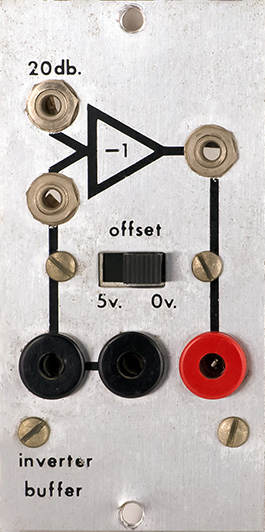
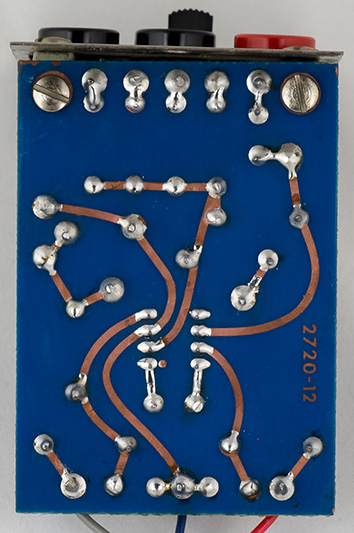
2720-12 Inverter Buffer
The Inverter Buffer was reasonably well built and did operate. I simply cleaned the switch and the PCB and touched up some of the soldering. It had some offset so I replaced the 748 op-amp.

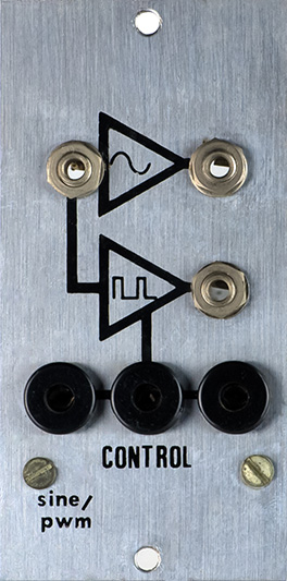
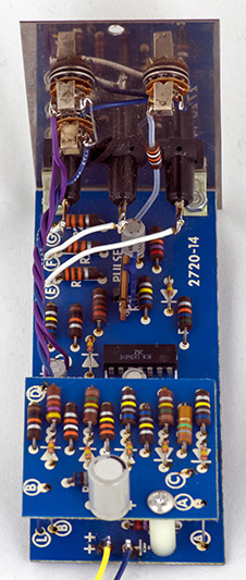
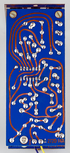
2720-14 Sine / PWM
This module was poorly built. I had to replace all the wires and resolder the entire PCB. I find it interesting that they included another PWM since the 2720-2A VCO has PWM. This must have been a companion to an earlier VCO although this module allows VC control of the pulse width.
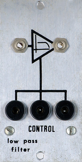
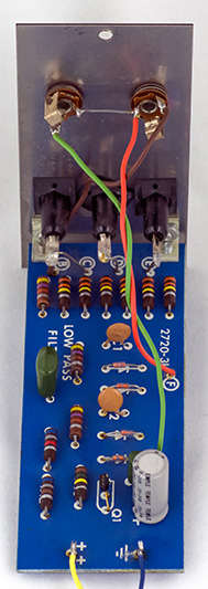
2720-3L Low Pass Filter
The Low Pass filter was reasonably well built and did operate. I cleaned the panel and the PCB, rewired the jacks, and cleaned up some of soldering.
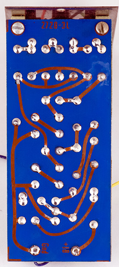
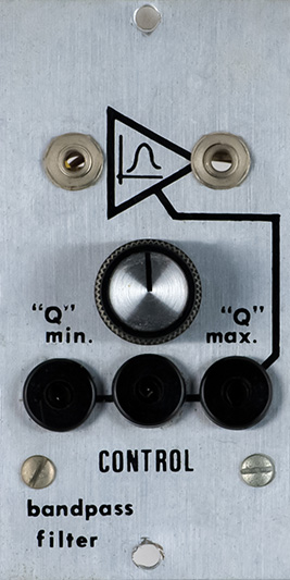
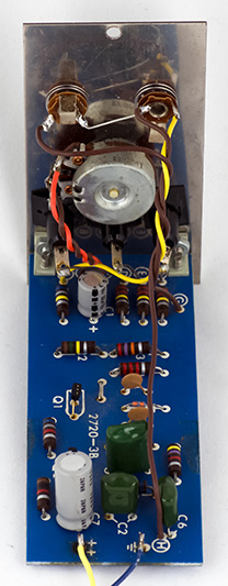
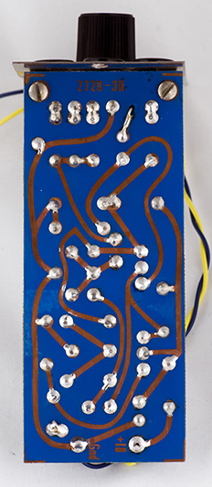
2720-3B Band Pass Filter
The Band Pass filter was reasonably well built and did operate. I cleaned the panel and the PCB, rewired the jacks, and cleaned up some of soldering.
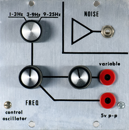
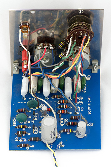
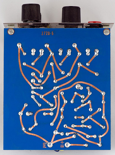
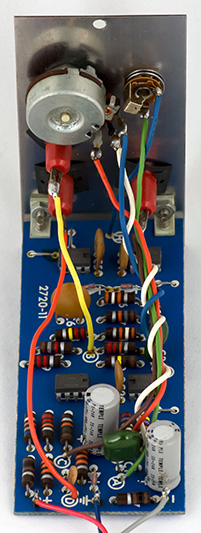
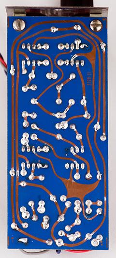
2720-5 Oscillator Controller
The Oscillator Controller is a sine wave LFO and noise source. I had to rewire all of the front panel connectors and clean the panel and PCB.
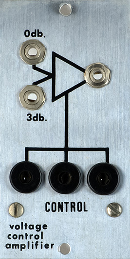
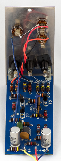
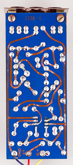
2720-1 Voltage Controlled Amplifier
I had to rewire all of the front panel connectors and clean the panel and PCB. I did note that the input to the VCA must be AC coupled and relies upon the output capacitors in the output of the other modules.
2720-11 Envelope Follower
The Envelope Follower was reasonably well built and did operate. I had to rewire all of the front panel connectors and clean the panel and PCB.

All complete! Most of the repairs were electro-mechanical in nature and improving the build quality from the original builder.
Epilog
I decided to upgrade all the pin jacks to banana. It makes the patching so much nicer and cables are easier to find. I also decided to upgrade the keyboard and rear panel potentiometers to locking style so to better resist bumps.
I also added a DC distribution board using 4 pin MTA connectors so modules could be easily unplugged.
I also upgraded the power supply with a combination external 5V supply and internal DC-DC converters followed by linear regulators. I used DROK DC-DC converters which provide 300 mA of current. A single DROK is used for +18V and a dual DROK is used for +/-9V. I adjust the DROK outputs for the PAiA to 2.5V higher and follow them with linear adjustable regulators to filter out switching noise. A DC in jack mounts on a bracket to mate with the cutout for the power cord.
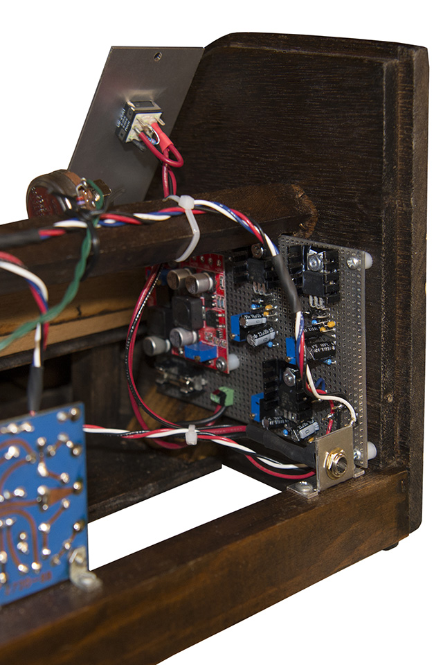
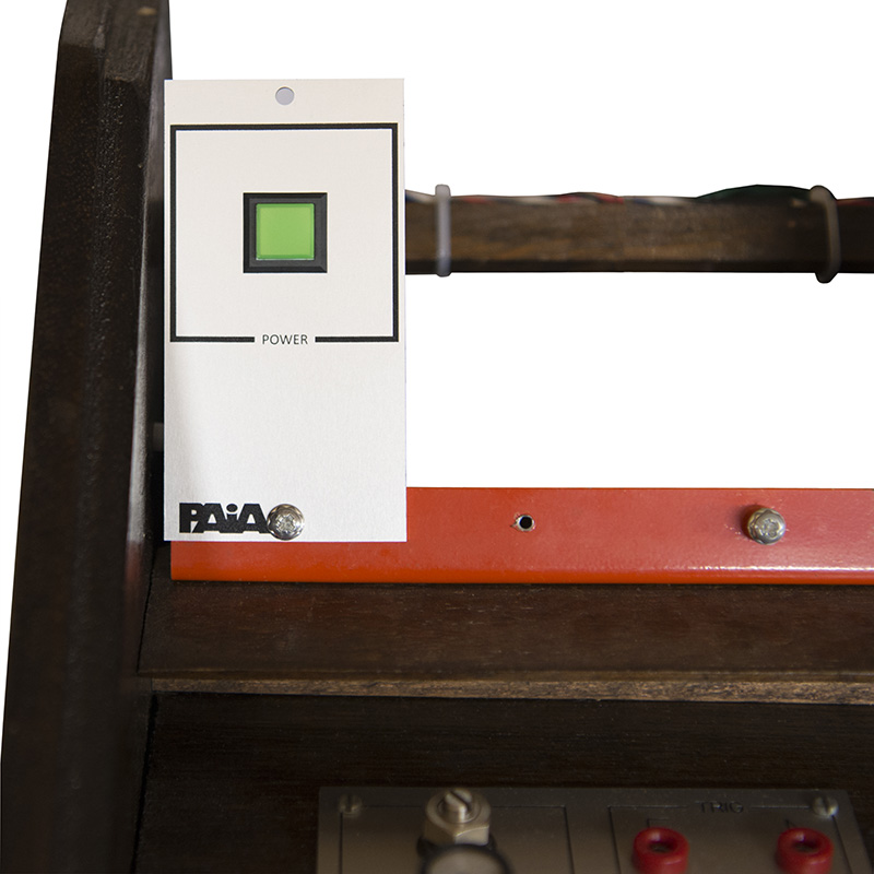
I made a new panel with an illuminated pushbutton power switch. You can see the locking pitch potentiometer in this photo.