|
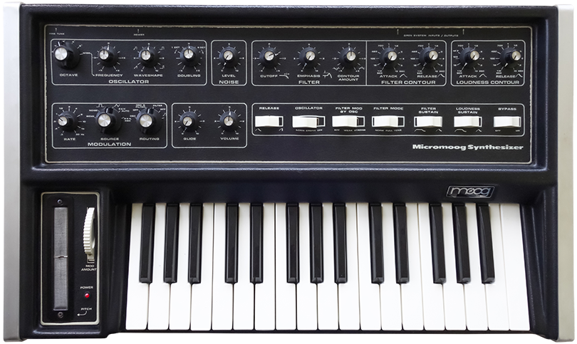
Moog Micromoog |
|
The Micromoog is a single oscillator synthesizer produced from 1975 to 1979. This one came into the shop for repairs so I took the opportunity for some photographs.
The schematics are typically in sections so I pieced them together in a single high resolution image.
The keyboard CV guard ring is on the schematics but I didn't understand it at first. I've highlighted it in red.
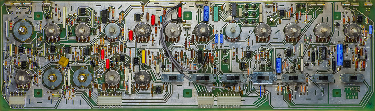
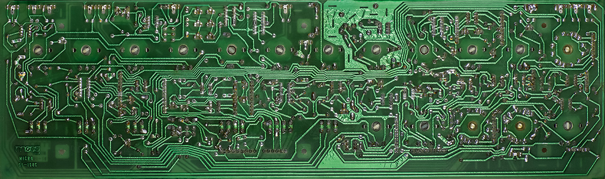
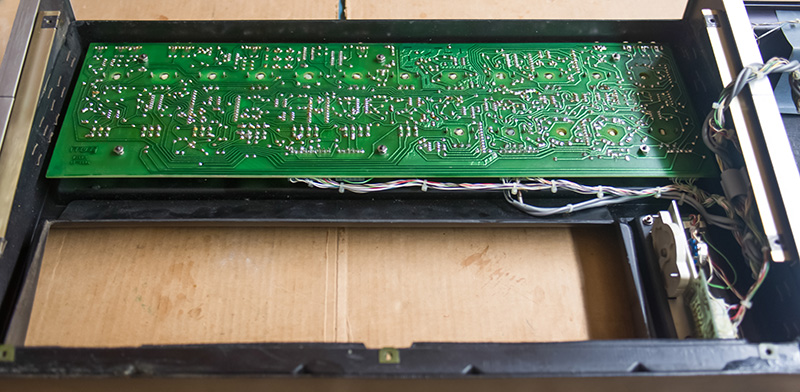
Main PCB
The potentiometers are mounted on the PCB only by the pins so the mounting isn't very robust. The PCB is double sided but without plated through holes so component runs have to be soldered on the top side. That makes it difficult for socket installation. This PCB had 4 sockets that I removed and a number of topside leads had to be resoldered. The large capacitor soldered at an angle above the bottom row second potentiometer from the left was a previous modification that I later removed.
Construction
The PCB mounts to the top cover and the connectors are somewhat hidden on the topside of the PCB. The cabling between the two halves is just barely long enough to set the top and bottom side by side. Working from the rear of the PCB is difficult so you can remove it and flip it over the keyboard cutout with suitable insulation underneath.
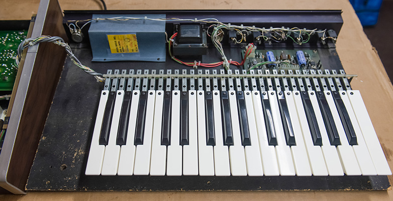
The bottom houses the keyboard, power supply and rear panel connectors.
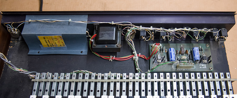
Here is a closer look at the power supply and rear jacks.
Repairs
This Micromoog came in for repairs for pitch instability and random triggering. The Micromoog used a single bus keyboard so the usual keyboard second bus was not available to generate the trigger. The designs adds a small 25 KHz triangle modulation into the current source for the keyboard then adds circuitry to detect this 30 mV signal on the keyboard CV and generate a gate from it. The triangle CV is above audio frequencies and is present only when a key is depressed.
The shield of the CV return from the keyboard is connected to a guard ring around the hold capacitor, glide circuitry, and JFET buffer. This guard ring is connected to the output of the CV buffer so it is held at the same potential as the CV. It is not very obvious on the schematics and I found this op-amp oscillated at 62 KHz at about the same level as the triangle waveform when a key is depressed. The detection circuitry would detect this as a key down and generate triggers. A 220 pF capacitor across R257 tamed the oscillations and turned the guard generator back into a guard ring.
I removed sockets, cleaned all the controls and switches, touched up soldering, cleaned flux, and backed-out previous modifications. The E402 had been replaced with discrete JFETs which I didn't think were the best choice so replaced them with a vintage FD1623 dual JFET. I cleaned the contacts but these were 40+ year old tin-on-tin connectors so I replaced the headers and housings with gold pins. In crimping the new terminals on I found a couple of wires that were nearly broken through. While I had the power supply out I replaced the two filter capacitors.
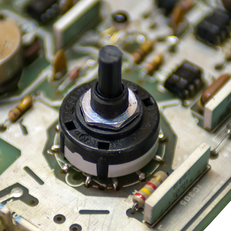
The Micromoog uses custom CTS 227 series switchs. The Octave switch was intermittent and the plastic housing was crumbling. I chose to replace it with a Lorlin CK1060 switch (Mouser 10SM160) which will fit with some modifications. The shaft is round and long so it needs to be cut to the proper length and flatted. It is a PCB mount and the two common pins will fit through the hole in the center of the PCB. The outer pins can be bent 90 degrees and wires soldered to them. I used four solid bus wires wrapped around the every third pin to anchor the switch firmly to the PCB. For the remaining 8 pins I simply bent and soldered solid bus wire. I test fit the switch first and determined the height of the shaft to cut.
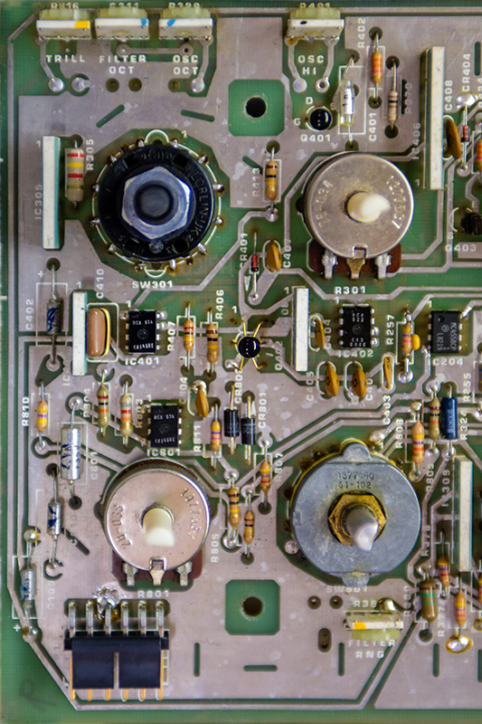
The nut has to be on to hold the stop ring but it is rather thick. I used a grinder to thin the nut and cut the plastic lock pin off. In retrospect, the shaft bushing was probably hanging up on the legend overlay since it has a smaller diameter hole than the case. I cut the overlay hole the same diameter as the case hole and it fits fine. This photo shows the new switch and gold header pins.
I had to jumper the switch common pins over to their pads.
The switch fits and works perfectly. Once it was installed, I used a hot X-Acto knife to cut the flat so it would align perfectly with the legend. In this photo you can see the thinned nut.