|
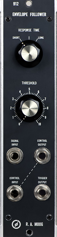
Moog 912 Envelope Follower |
|
The Moog 912 Envelope Follower consists of two separate functions. The first function is an envelope follower with a short, medium, and long response time which produces a DC control voltage proportional to the envelope of an input signal. The second function is a variable voltage comparator with an S-Trigger output. The envelope follower control voltage output is interfaced to the comparator through a normalled jack connection. This latter 912 module uses a 1/4" jack instead of the more common Cinch-Jones 2-pin S-Trigger connector. There is an error in the input signal circuit so I corrected it in this PDF file.
Correct 912 Envelope Follower schematic
The PCB on this module show etching problems so the very bottom run was jumpered on the top.
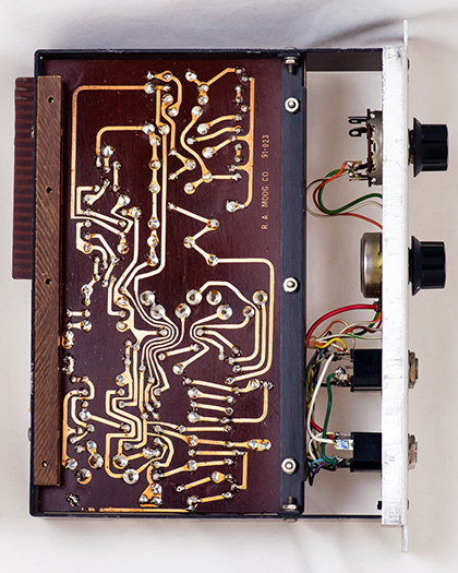
The brown wire at the bottom jumpers the badly etched trace.
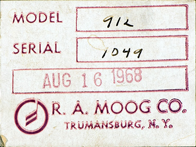
Moog did not give modules serial numbers until 1967 and started at serial 1001 so this is the 49th 912 produced after assigning serial numbers.
Operation
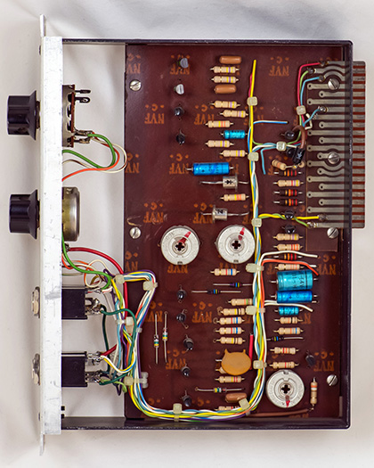
The first section of this module is an envelope follower. There are three calibration trimmers for this section and two of them interact quite a bit so trimming was time consuming. The envelope follower is really designed for low level inputs although it will take up to a 4V pk-pk signal. I calibrated the module using a 250 Hz 500 mV pk-pk sine wave input.
| Voltage In (pk-pk) |
Output (Specified) |
Output (Measured) |
| 31 mV | 2.4V | 2.6V |
| 127 mV | 3.5V | 3.6V |
| 500 mV | 4.5V | 4.5V |
| 1V | 5.0V | 5.0V |
| 2V | 5.5V | 5.4V |
| 4V | 6.0V | 5.8V |
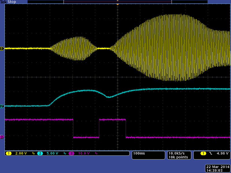
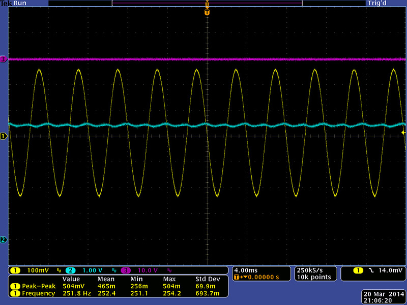
This scope image shows the Signal Input and Control Output. The yellow trace is the 250 Hz 500 mV pk-pk Signal Input, the cyan trace is the Control Output with the response time set to short, and the magenta trace is the Trigger Output. Although the Trigger Output is a 1/4" jack the output is a S-Trigger and is pulled up externally so is true in this scope image. Changing the response time to long smoothed the ripples in the Control Output.
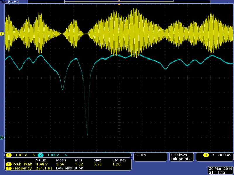
This 10 second scope trace shows the Control Output response to a varying amplitude Signal Input. The Control Output stays in the 3 to 6 volt range when the Signal Input is in the range of 63 mV to 4V pk-pk. This module must have been designed for low level inputs like guitars and microphones.
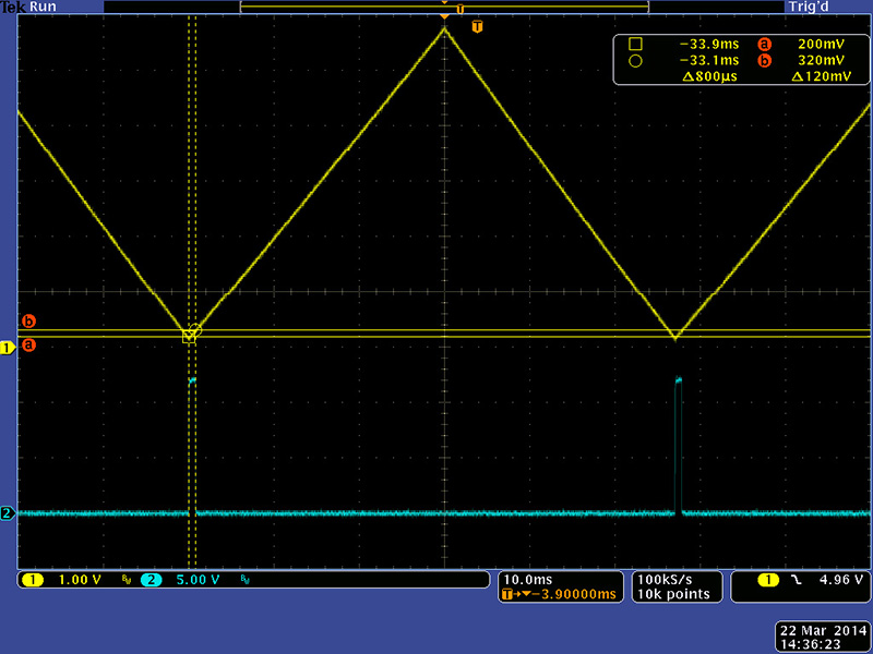
The second section of this module generates a S-Trigger whenever the Control Input is greater than the Threshold control. The Control input is normalled to the envelope follower Control Output and has hysteresis to eliminate jitter. This scope image shows a 320 mV setting for the Threshold with 120 mV of hysteresis.
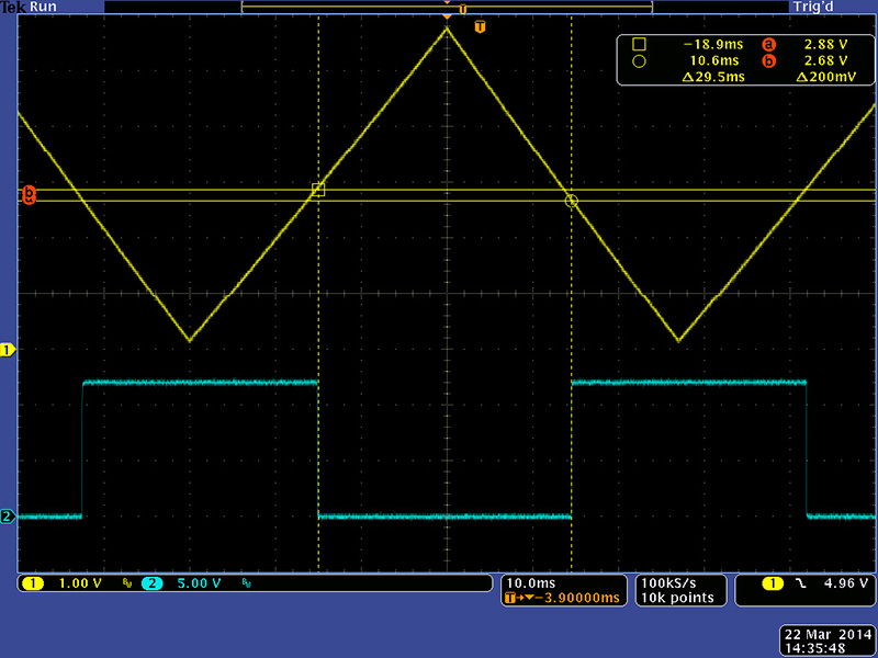
This scope image shows a 2.88V setting for the Threshold with 0.2V of hysteresis.
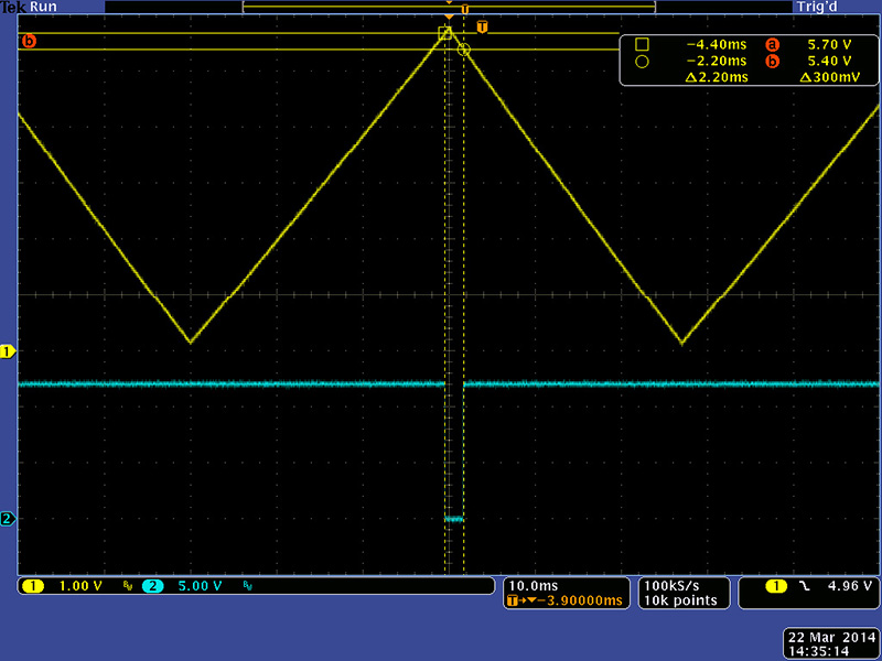
This scope image shows a 5.7V setting for the Threshold with 0.3V of hysteresis.
This scope image shows the envelope follower operation with the Control and Trigger Outputs with the Threshold set to 5V.