|
Moog 902 Voltage Controlled Amplifier |
|
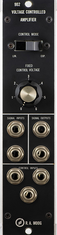
The Moog 902 Voltage Controlled Amplifier has both linear and exponential response. The two inputs are differential and are normalled to ground. The lower input jack is subtracted from the upper input jack, not added. The two outputs are differential and the upper output is inverted. So to keep the phase of a single input the same you would use opposing jacks - upper input and lower output.
This 902 is earlier than the schematics and is missing the P4 trimmer. I had a hard time balancing the stages following the directions on the schematics which start from the output. Instead I started at the inputs and balanced each of the three stages. Then I could adjust the output level to close to 0 volts over the range of the control with no input. The exponential mode output was quite low and so I hand selected the resistor where P4 would be to equalize the linear and exponential outputs.
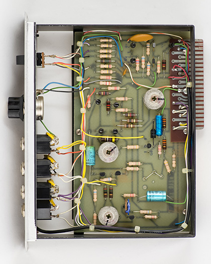
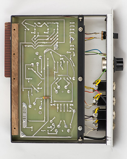
I had to change some of the collector resistors to get the differential stages to balance. The resistor on the back is a tweak to one stage to bring it back within the range of the trimmer.
These two modules are sequential and number 118 and 119 built. They are an earlier version that does not quite match the schematics. Moog did not give modules serial numbers until 1967 and started at serial 1001 so these are the 118th and 119th 902s produced after assigning serial numbers.
Operation
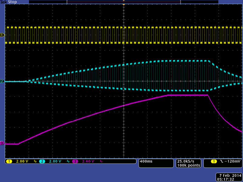
This scope image shows the output of the 902 Voltage Controlled Amplifier driven by a 911 Envelope Generator. The input is in the top jack and the output is from the top jack. You can see the signal inversion in this scope image.