 |
Moog 901-B Oscillator |
|
The Moog 901-B Oscillator was the initial VCO designed with a unijunction transistor ramp generator. The 901-B Oscillator is controlled by the 901-A Oscillator controller which provides +12V for the ramp core circuit, control voltage, and the pulse reference voltage. Module cabling is wired in parallel so that a single 901-A can control up to three 901-B modules. The very left range position is for LFO operation.
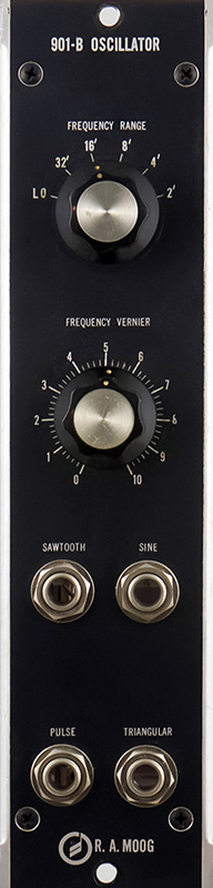
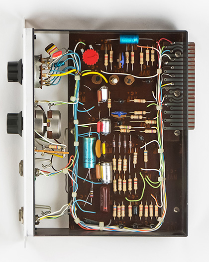
The 901-B Oscillator is a 1 MU wide module. The original tracking resistor has been replaced with the red tracking trimmer. You can see the parallel capacitor combinations to pad the range switch settings.
Operation
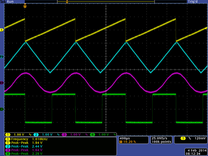
The ramp output is converted to a triangle output with a unique two transistor circuit and to a pulse output with a voltage comparator. The triangle output is shaped with a diode circuit to form the sine output. All four outputs are different levels specified in RMS voltages. I always measure outputs in pk-pk on the oscilloscope so use these conversions.
| Output |
RMS |
Pk-Pk |
| Ramp | 0.50V | 1.73V |
| Triangle | 0.65V | 2.25 |
| Sine | 0.50V | 1.41 |
| Pulse (50%) | 1.20V | 2.4V |
The ramp output has a symmetry adjustment but the other three output levels were not symmetrical about ground so I adjusted them with resistor value changes. The outputs are pretty well formed. There is a small glitch at the top of the triangle which has a capacitor filter to minimize it. The output amplitudes vary a bit from the specifications.
There are more scope images on the 901 Oscillator page.