|
Buchla Format MIDI Module |
|
I wanted a MIDI module for my Buchla. I didn't need anything overly fancy with a lot of outputs so decided to build one using the Oakley midiDAC. The PCB is 0.050" narrower than a panel so will just barely fit.
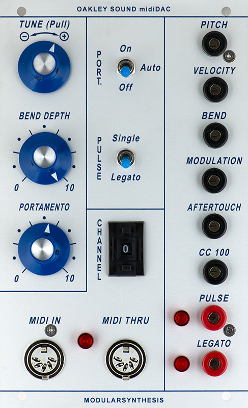
I designed the panel using printed graphics on anodized aluminum panel from FrontPanelExpress.
The PCB will mount with the components facing the panel so I mounted the trimmers so I could access them from the side. +5V is available so I deleted the various parts for the local +5V regulator. I had to cut a trace under D12 and replace it with a 2R2 resistor. I did not install any of the reverse or over voltage protection diodes since the Buchla supply is keyed. I did not use any connectors since the power cable and front panel components will be hand wired.
I need several modifications for this PCB. Increasing R24 to 12K changes the CV range to 1.2V.
I added a MIDI LED from U10 pin 3 to +5V through a 2K2 resistor.
I changed the Tune potentiometer to one with a pull switch so I can disable it.
I wanted a way to turn off portamento so needed to cut a run between U10 pin 2 and U6 and R16. I can use the unique feature of a 1P3T switch to break this connection and tie the inputs of U6 and R16 to +5V to disable portamento. The other half of the switch can be used as the normal SLID switch.
I needed Buchla 10V trigger/gate and used a CD4504 level shifter to boost the 5V gate to 15V. Three resistors and a capacitor drop it to a 10V trigger and 5V gate. Likewise for the Legato a level shifter and two resistors boost it to 10V. Since there are six level shifters in the package I paralleled three for each output to increase the source current capability. To parallel the sections I bent the some of the legs inwards and then added bus wires across the three sections on the inputs and outputs. I used double-sticky foam to mount the IC upside down on a bare area on the board. After this photo was taken I replaced the upper left resistor with a Schottky diode and 4.7V zener for a better pulse output.
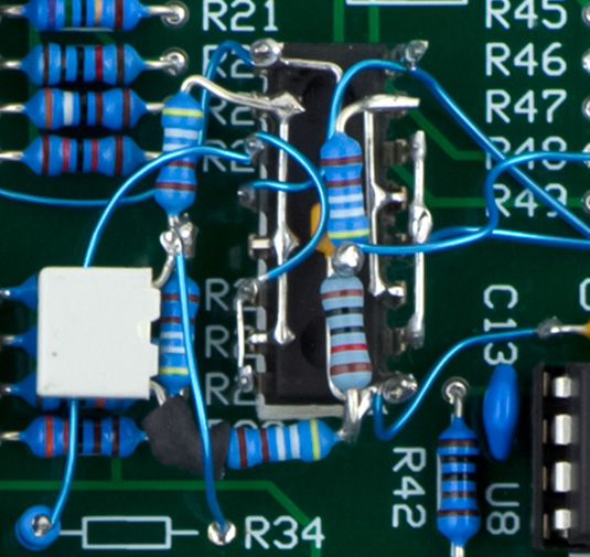
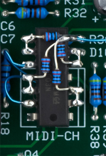
I had panel space so added a thumb switch for MIDI channel selection. This thumb switch is all open for "0" while the DIP switch is all closed for "0". I added a 74HC03 open-collector inverter with input pullups to invert the signals from the thumb switch. I could get three of the legs into the DIP switch pads so bent the other legs up to wire. I used 1/8W resistors to better fit on top.
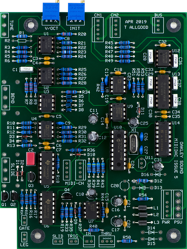
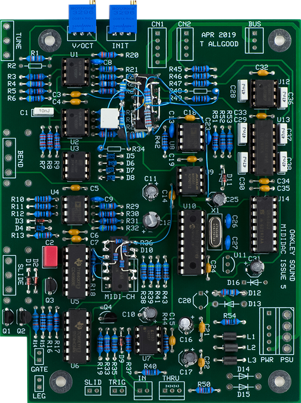
Here is the board with the modifications. It was a bit tedious to wire.
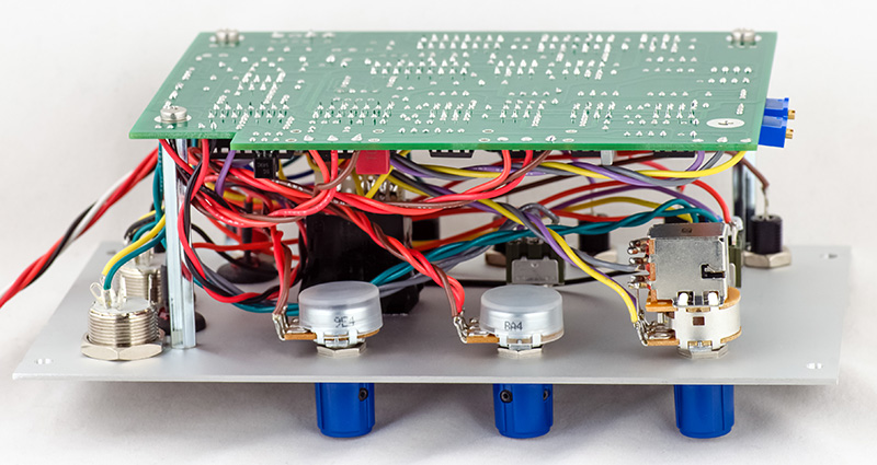
It was even more tedious to wire up the panel especially with the additional panel switches.
Modifications consisted of eliminating the on-board +5V supply, increasing the legato output to 10V and creating a 10V trigger/5V pulse, adding a MIDI LED, expanding the On/Auto portamento switch to include Off, adding a pull switch to Tune, changing the scale to 1.2V/Oct, and converting to a front-panel MIDI channel switch.
Operation
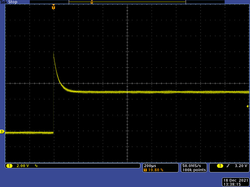
It works great. This image shows the modified Pulse out as a 10V trigger and 5V gate. It is only driven high so may be paralleled with other pulse outputs.