|
Hammond M-2 and Leslie 45 |
|
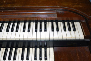
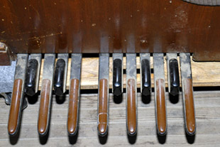
I picked up a Hammond M-2 and a Leslie 45 for free. The M-2 organ is a basic no-features tonewheel spinet that was produced from 1951 until 1955. It has a single set of drawbars for each manual and a single octave of monophonic bass pedals. There is no percussion or reverb. The organ was complete but needed considerable work including the finish.
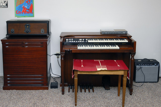
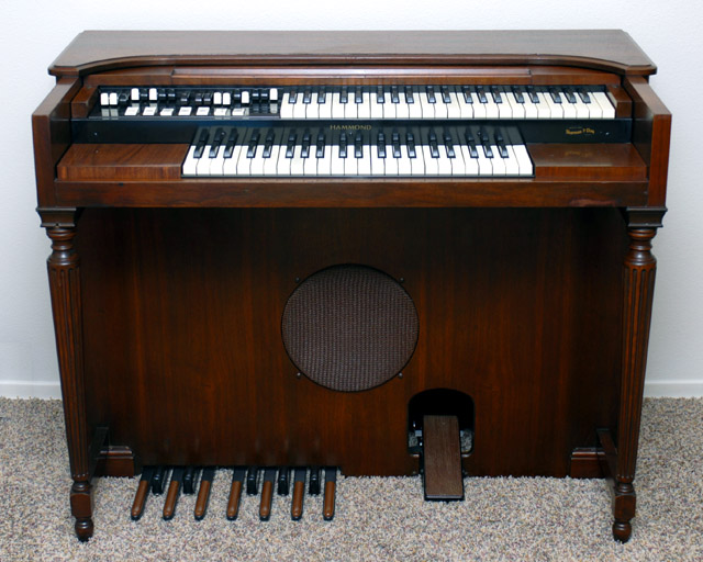
Here is the restored M-2 with the Leslie 45. The Leslie control box is on the floor between the two. On top of the organ is an Ibanez DM-500 digital delay connected to the M-2 direct out. The digital delay drives a Fender 25r that also adds a bit of reverb. I am using all three amplifiers and speakers in this setup - the Leslie provides a chorus channel, the M-2 provides the dry channel, and the Fender provides the delay and reverb channel. On top of the Leslie is my restored Radiola 60 radio, circa 1928.
M-2 Restoration
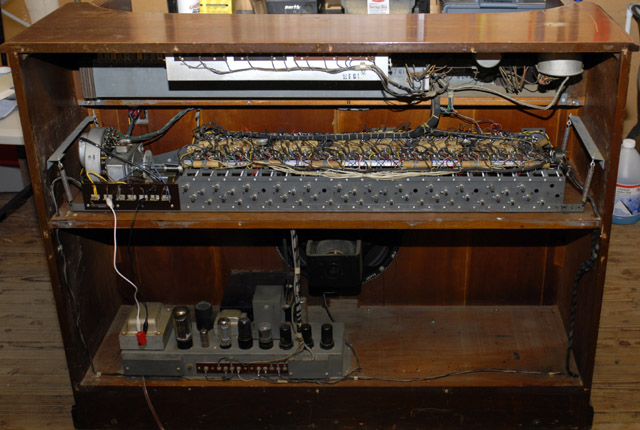
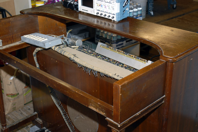
I removed all of the modifications that had been made for the Leslie and an external line out. I had to repair the speaker wires where they connected to the chassis. The insides of the organ are fairly clean. The run switch was replaced previously and wired incorrectly so another resistor was added in parallel with the start resistor. I replace and rewired the switches and oiled the scanner and tone wheel generator. I also oiled the starting motor gears and had to adjust them slightly to get them to mesh without chattering. You can see my 'remote starter' clipped to the power strip as I couldn't reach the front start switch when working on the start motor.
The organ needed serious cleaning as the keys, drawbars, and pedals are covered with cigarette smoke. The drawbars are quite intermittent but the organ does play and everything functions! I removed most everything except the tone wheel generator to give it a thorough cleaning. This organ took a lot of work to restore.
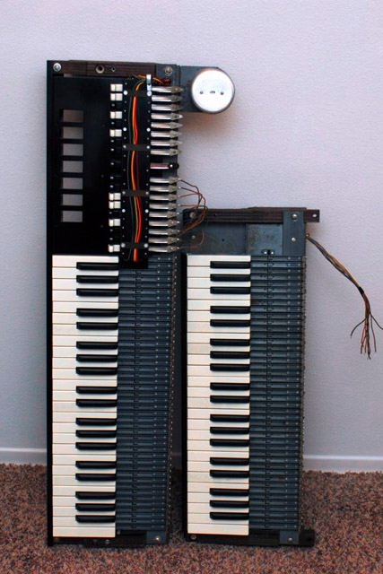
I unsoldered the wires to remove both the upper and lower manuals. It is easier to remove the lower manual first to have better access to the upper manual terminal strip.
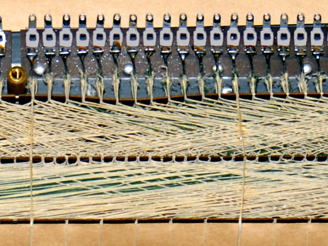
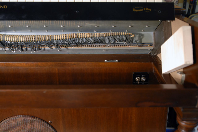
Here is the underside of the lower manual with the cover removed showing the resistance wiring from each key contact to the rear terminal lugs. The resistance wiring is impressive. The wires are routed diagonally in cardboard guides and bound with string.
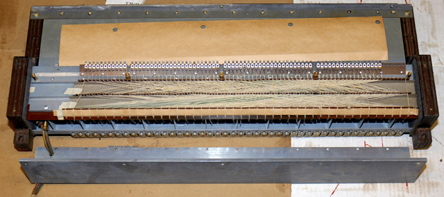
Here is a close-up showing the precision of the wiring bends and routing.
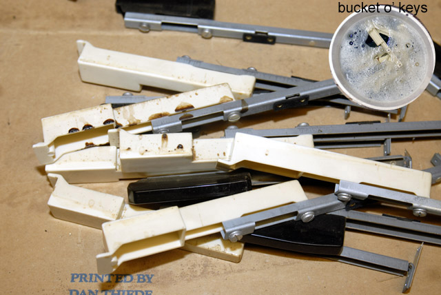
I removed all the key tops for a thorough cleaning. They were filthy and need soaking. I can only imagine the amount of drinks that were spilled onto this organ.
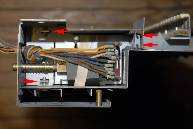
I dismantled the keyboard as far as I was comfortable for cleaning. The keyboard is assembled with screws from both the top and bottom into center bars that compress the sections together. You can see the bus bar adjust mechanism and also the construction of the keyboard assembly where the screws sandwich the center section with two bars (leftmost arrows) that run lengthwise. You can also see the ends of the two small rods (rightmost arrows) that hold small face plates to seal the key contact area between felt . The keyboard has a very unique assembly technique and is quite solid.
The busbars were covered in oil, both wet and hardened. I had to completely disassemble them and clean absolutely everything. There are a lot of pieces to these drawbars. There are two contacts in the end of each drawbar assembly. One contact is isolated from the drawbar with a 1 ohm wire connecting it to the drawbar.
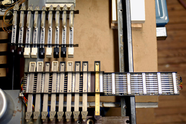
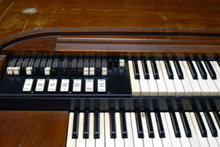
The manuals and the drawbars cleaned up nicely!
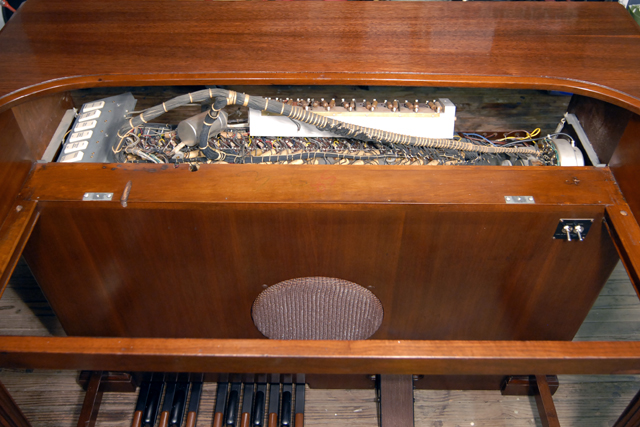
There was candle wax all over the speaker grill, pedals, and the front of the organ. I removed the wax from the hard surfaces with a putty knife. I removed the wax from the grill by pouring hot water through it and cleaned the cigarette smoke off with a thorough cleaning in the sink. The wax had splashed through the grill and onto the speaker cone. It didn't stick very well so I was able to scrape and brush the wax off the speaker cone.
I removed the left leg which the brace was broken off at the front of the organ. I drilled a 1/4" hole through the remaining brace piece in the organ and a 1/8" matching pilot hole in the matching leg brace. I glued and bolted the two halves together with a 6" x 1/4" lag bolt from the inside of the organ accessed from underneath. The leg is now very secure!
I thoroughly cleaned the sides, legs, and front of the organ with Howard's "Restor-A-Finish". It's starting to look decent now except for the top which has seen a lot of abuse. With the manuals removed, I decided to try and refinish just the top. I wrapped the organ in protective plastic and carefully stripped the finish. I removed the deep scratches by finish sanding with 220 grit.
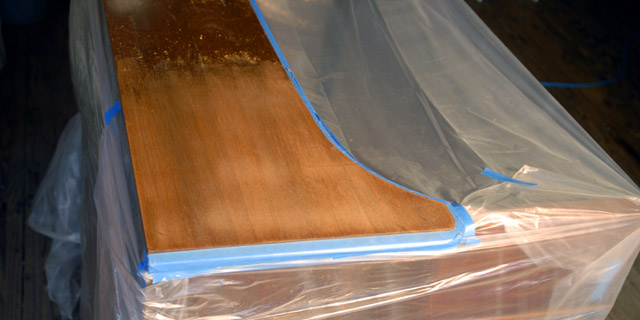
A blend of red oak and walnut stain matched the original color pretty well. I finished the top with six brushed coats of gloss lacquer, wet sanded with 320, 400, 600, and 1500 grit, and then hand polished. It really looks nice.
I raised the organ to more easily resolder the 88 wires to the manuals.
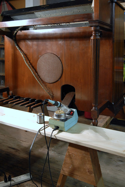
Here the upper manual is raised on blocks with cardboard spacers to protect the wood side panels. It is much easier to resolder the wires with the lower manual still out.
All restoration work is complete and the organ plays very nice. I made a direct-out box using a surplus power transformer and a couple of resistors. The transformer isolates the ground and works well over audio frequencies. The resistor attenuators reduce the signal to an appropriate level for an instrument amplifier.
Zinc Whiskers
As I was working from the rear soldering the matching transformer wires I had a good view of the tone wheel generator chassis in bright lighting. I thought that the chassis was dusty but instead it was covered in whiskers. Zinc whiskers are crystalline structures that grow in the shape of a thin hairs emerging outward from a zinc surface. I've posted several close-up photos of the zinc whiskers. Great
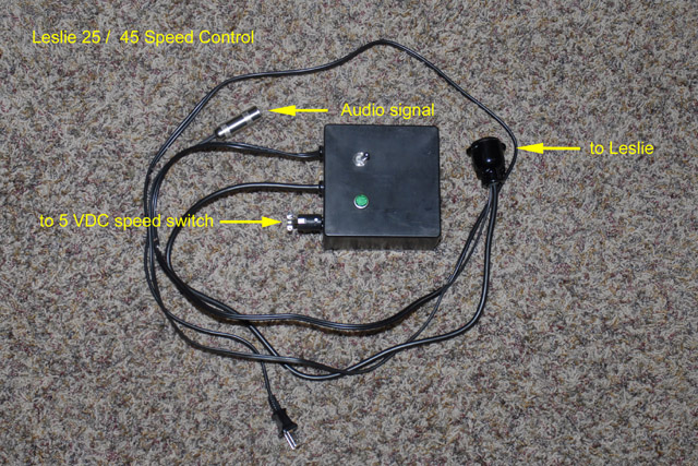
Leslie 45
The Leslie 45 is single speed rotor with a 15" speaker and horn with an optional amplifier. The cabinet was cracked on both sides which I glued and reinforced with metal brackets. I made a small control box with a line cord, switch, fuse, and a solid state relay for 5 volt switch contact control of the speed. I installed a Leslie 225 amplifier by moving the control box to the side and adding a small pigtail connector to mate with the amplifier signal and power cable.