 |
DJB-ComputerVoltageSource |
|
I worked with John Loffink to co-develop the LCD display module. The design is an adaptation of my PSIM display module using an ATTINY2313 microcontroller with an 8 MHz crystal. I adapted the code to use the 14 pin parallel interface to a standard 2x16 LCD.
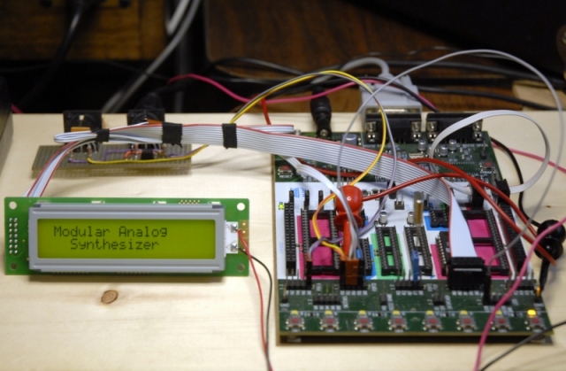
Here is a photo of the development environment using the STK500. I used a 2x20 display for the initial code development and later adapted this to also support 40x2 display. A PSIM MIDI interface is the board behind the display in this photo.
This video demonstrates using the display to set a number of parameters for the SuperSequencer program.
This video demonstrates the performance of the display used as eight output level indicators for my CVS Joystick Generator program. The numbers correspond to the output channels, the symbols indicate the quadrant of the joystick, and the bar levels were created using the programmable characters.
Design Information
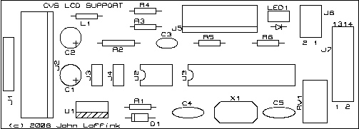
John Loffink designed the LCD_Support PCB which interfaces directly to the back of the LCD module.
CVS
LCD Schematics and Design Documentation
Complete documentation
including software guide, schematics, parts list, PCB layout, component placement,
and FAQ is located in
the LCD_Support folder in the files section on the Yahoo
ComputerVoltageSources
group.
Here is the PCB layout.
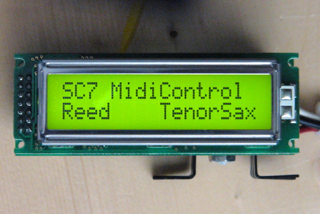
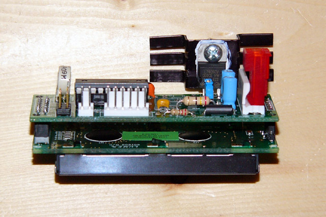
Here are photos of the LCD and assembled display module. I later reduced the backlight brightness which sufficiently reduced the power so I could eliminate the heat sink.
Display Functionality
The LCD software checks for a MIDI sysex command with educational ID=$7d and processes characters contained in the message. Once a sysex message has been started, characters may be sent irregardless of timing and the LCD software will update the display appropriately. All non-LCD sysex commands are sent to the MIDI output so display messages will be filtered.
The software supports the following
display commands:
0x08: (backspace) Moves the active display position one backwards
0x09: (tab) Moves the active display position
one forward
0x0a: (line feed) Clears the display and sets
the active display position to beginning of line 1
0x0b: (vertical tab) Sets the active display
position to beginning of line 2
0x0c: (form feed) Clears the display and sets
the active display position to beginning of line 2
0x0d: (carriage return) Sets the active display
position to beginning of line 1
0x0e: (shift out) Selects the lower characters
set for display
0x0f: (shift in) Selects the upper characters
set for display
0x10: Program Character0
<data>,<data> … <data> (8 bytes total)
0x11: Program Character1
<data>,<data> … <data> (8 bytes total)
0x12: Program Character2
<data>,<data> … <data> (8 bytes total)
0x13: Program Character3
<data>,<data> … <data> (8 bytes total)
0x14: Program Character4
<data>,<data> … <data> (8 bytes total)
0x15: Program Character5
<data>,<data> … <data> (8 bytes total)
0x16: Program Character6
<data>,<data> … <data> (8 bytes total)
0x17: Program Character7
<data>,<data> … <data> (8 bytes total)
0x18: Sets the display mode to overwrite; new
characters overwrite previous
0x19: Sets the display mode to scroll; display
scrolls for new characters
0x1a: Sets Absolute Position <data> (2
bytes total)
0x1b: Sets Relative Position <data> (2
bytes total)
0x1c: Reserved
0x1d: Reserved
0x1e: Reserved
0x1f: Write
Message <data>,<data> … <data> (33 bytes total)
The Write Message command stores a new default power-on message in the eeprom to personalize the module.
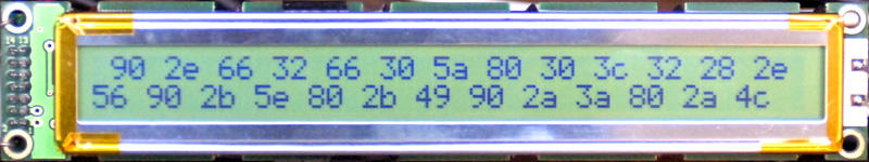
There is a second mode that will operate with a special build option of the PCB which supports a scrolling MIDI monitor display. All MIDI data received will be displayed in a scrolling hexadecimal format, passed through to MIDI out, and indicated by an indicator LED. A MIDI monitor power-on message is displayed and is cleared by the first MIDI data received.
This special build PCB configuration has MIDI input and output circuits which can be used to provide MIDI and display functionality for the SynthModules.com PSIM. A single 4 pin cable connects this module to the PSIM.
Here is a photo of the MIDI monitor display in my custom 2x40 version.
A complete software guide is here and also on the ComputerVoltageSources Yahoo group in the Files>LCD Support folder.