|
4U 200 Series Turing Machine Module |
|
I received this PCB set from an individual I helped. It is a 4U derivative of an Eurorack module as described on the Modwiggler thread 4U/LW Alan & Friends, a take on the Turing Machine thread.
"For those who have not heard about the Turing Machine, a popular Eurorack module, it is easily described as a controlled-random looping sequencer. Basically, it spits out sequences of notes, in a random fashion, since your only control over the sequence is the amount of randomness.
In this version, I added some expanders directly on it (those related to sequencing) to make it a meta-random sequencer.
It has multiple trigger outputs, two CV outputs, and can work as a noise source. It only needs a clock input.
It also has the original expanders connectors on the back, so that you can use existing ones.
I modified a bit the circuitry from the original, so the clock should be more robust and the noise source a bit louder; the tuning procedure is also easier. Also, I made some design choices (omitted some outputs on Pulses, less LEDs than in the original...).
Oh, and with the right panel there is no reason that it could not be used with R*S format, since it's 4 rows. It could theoretically work with Buchla too, the CVs are positive and +/-15V should be OK."
From the Music Thing Modular website:
The Turing Machine makes music for you. It's a binary sequencer, based around a 16 bit memory circuit called a shift register. It's a sequencer that you can steer in one direction or another, not one that you can program precisely.
You cannot program this sequencer to play specific tunes. You cannot save sequences. You can never go back to a sequence that has changed.
To put it another way: the Turing Machine produces clocked stepped randomly changing control voltages. In other words, melodies, bass lines, sequences. Unlike many random voltage generators, these sequences can be locked into loops that repeat according to the length control.
Musically, the module was inspired by 60s and 70s minimalist process music by people like Steve Reich, Terry Riley or Philip Glass: "I am interested in perceptible processes. I want to be able to hear the process happening throughout the music. To facilitate closely detailed listening a musical process should happen extremely gradually." Steve Reich, Music as a Gradual Process, 1968.
I made modifications on the font and size to better match my other 4U modules. This is a printed FrontPanelExpress design.
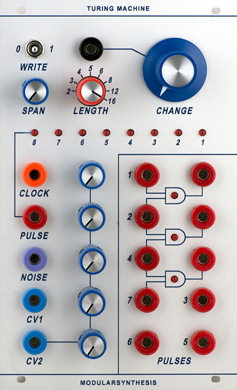
I had to review the schematics to understand all the controls and functions (includes modifications for 10V outputs).
- Clock input threshold is 3V with hysteresis. Pulse outputs are true when the clock is true.
- CV1 is the binary sum with a 10V range of stages 1 - 8 attenuated by the Span control. Stage 8 is msb.
- CV2 is an equal weighted sum of stages 1 - 5 attenuated by the individual controls. Maximum output is 10V. Stage 1 control on top.
- Change control is +/- with center ~0V. Length selects what feedback tap is used for the input to stage 1. It is inverted if Change > Noise.
It is overwritten by the switch.- Pulse outputs for stages 1 - 7 are on the right and pulse for stage 8 is below the clock input. Pulse outputs are 10V.
- RC delay between stages 4 and 5, 8 and 9, and 12 and 13 with a time constant is 10µS so N/A.
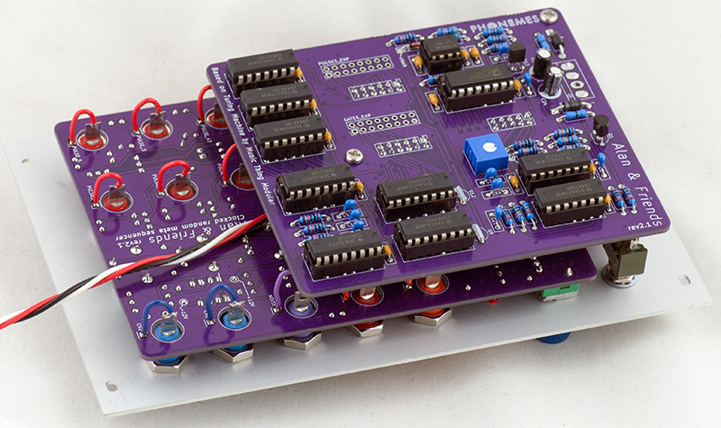
Construction
It is built on two PCBs and only the banana jacks and the switches are panel mounted. I made resistor changes for 10V pulse outputs.
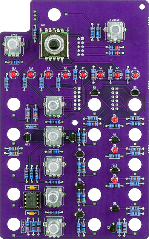
Most of the logic is on the rear PCB. I did not install any of the expansion connectors.
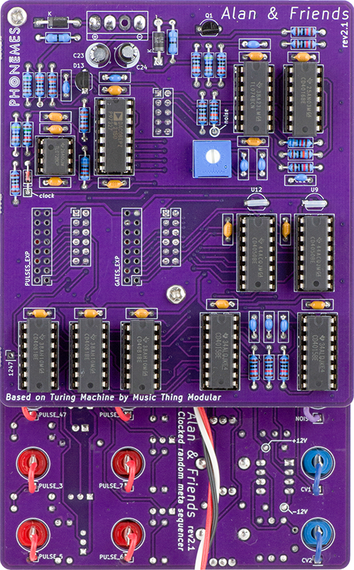
I didn't use the rear MTA156 connector to minimize the depth of the module and brought the power cable out from under the rear PCB. This module requires only +/-15V.
Operation
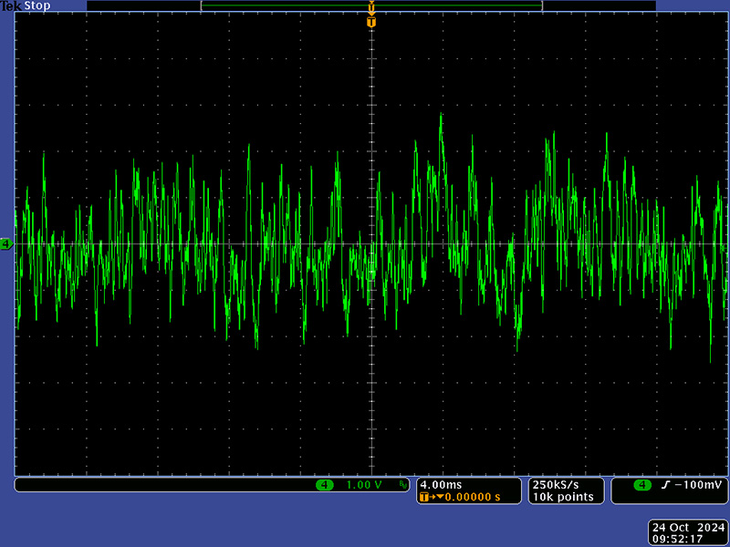
Operation is pretty simple. You supply a clock as the only input. The pulse outputs are the width of the clock input. This scope image shows noise adjusted to +/-2V pk-pk. See below for how I finally calibrated noise.
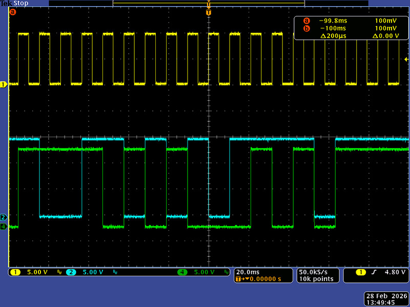
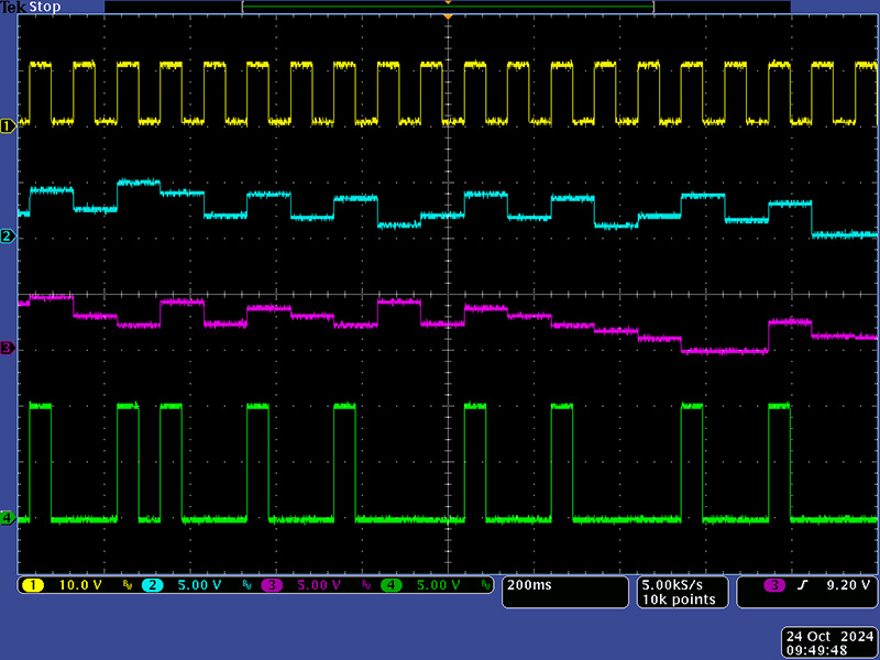
This scope image shows the Clock, CV1, CV2, and Pulse.
Design
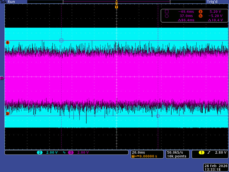
I was helping via email to debug a module so took a deeper dive into the randomization. The Change control provides a +/- Vcc range, so +/-7.5V since I am using +/-15V supplies. I assume that there should be a dead zone at each end of the Change control so adjusted the noise level such that I had a bit of margin. The operative range is about 9 o'clock to 3 o'clock. I set my scope to envelope (infinite persistence) and rotate the Change control over it's range (cyan). This scope photo shows the magenta random level at about +/-5V.
The comparator output then drives the inversion circuit here the last bit in the shift register as selected by the Length switch is inverted if the noise level is less than the Change control. The inversion circuit works such that at the Change CCW position the last sequence bit is always inverted and at the CW position it is not inverted. To 'freeze' a pattern you simply rotate the Change control to CW. The maximum randomness occurs at mid position and decreases in either direction.
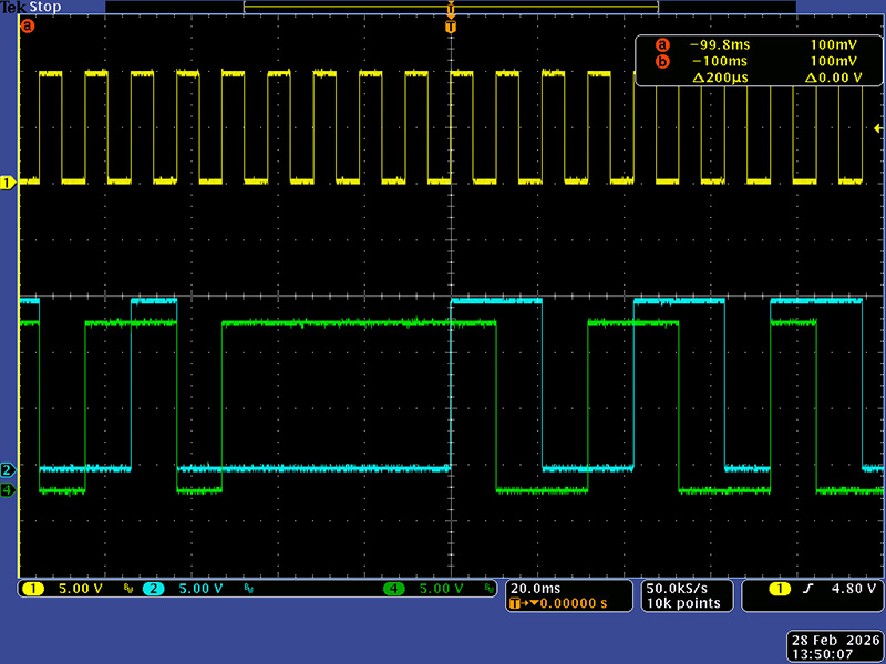
This scope image shows the sequence end bit (cyan) vs the first stage Q output (green) at the Change control CCW position. Note the green bit one clock cycle after the cyan bit is always inverted.
This scope image shows the sequence end bit (cyan) vs the first stage Q output (green) at the Change control mid position. Note the green bit one clock cycle after the cyan bit is sometimes inverted showing the randomness.