 |
232 Frequency Detector Module |
|
This is one of very few 1972 Buchla frequency detector which came from Mort Subotnick. It was sent to me to check out and calibrate. It has a collection of different circuits with a tracking VCO, pitch to CV, pulse generator, and transfer gate. I suspect the original purpose was for tracking an acoustic instrument or the human voice to drive various synthesizer modules. It might have been used as part of the Ghost Controller setup.
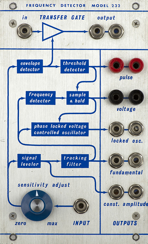
The signal leveler is automatic gain control (AGC) circuit which provides a constant amplitude signal for processing. It also contains a 60 Hz notch filter and a tracking bandpass filter. A reasonable input signal level is about 500 mV pk-pk indicating more of a traditional line level input from a preamplifier output. The constant amplitude signal begins to distort about 1V pk-pk input.
The tracking filter reduces the input signal to its fundamental frequency. The frequency detector generates a CV which drives a phased locked VCO which tracks the fundamental frequency to provide the locked oscillator output.
The output of the tracking filter also drives an envelope follower with a threshold level which generates a trigger/gate (pulse) output. The internal gate also drives a track & hold (sample & hold) on the CV output. Use of the track & hold allows the module to hold the last valid CV when the input signal disappears and the locked oscillator drifts.
An independent transfer gate is also controlled by the envelope detector. The locked oscillator if patched, or other external signal, can be processed by the transfer gate to follow the input envelope including muting when the input is removed.
I can envision this module to provide a CV pitch and VCA to allow control by an acoustic instrument. The VCO output, pitch CV, and Pulse outputs could be used to drive various synthesizer modules and the resulting signal run through the Transfer Gate. The CV output is not a fixed V/Octave over the frequency range but is in the range of 4V/Oct.
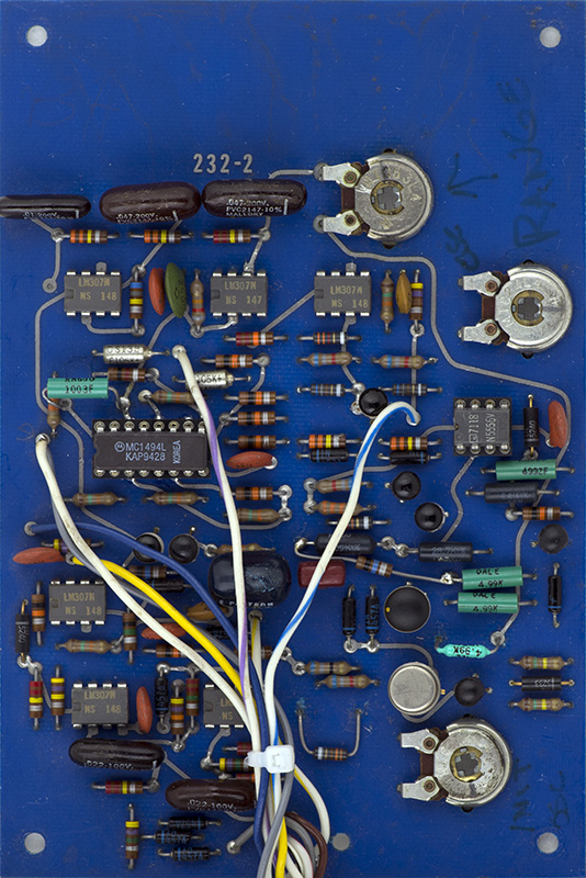
I don't disassemble vintage modules more than I have to so I only have photos of PCB2. This contains the phase locked loop, VCO, and CV sample & hold. However, my MEMS 232M page does show the reproduction panel wiring and PCB1.
Bench Check Out
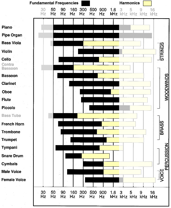
The specified frequency range of the 232 is 80 to 2500 Hz. While I could get the oscillator to lock over this frequency range, I could not get it to track without readjustment. There are 4 trimmers for level, scale, offset, and sine shape. Trimming is challenging in that the scale and offset both effect the scale of the locked oscillator. I first tried to scale by stepping the input frequency over octaves and adjusting the scale of the locked oscillator for similar octaves. Once scaled I then adjusted the offset to lock to the input frequency. This method had issues locking over the frequency range. I tried an iterative method of adjusting the scale and offset to find the widest range possible for locking but found numerous settings which tracked range edges, but not over a wide range. I decided to not fight the phase locked loop so removed the MC1496. I could then adjust the scale to closely track the incoming frequency interval and then adjust the offset. Once I reinstalled the MC1496 I had to adjust the offset and was able to achieve 25 Hz to 2000 Hz. While I could trim to reach 2500 Hz, it then wouldn't track at lower frequencies. I decided to leave it from 25 Hz to 2 KHz. Large steps in frequency noticeable time to lock.
This chart of frequencies from the Fundamentals of Room Acoustics, by Octavio Inacio, used with courtesy of the Polytechnic Institute of Porto, shows that this frequency range includes a large range of instruments including the human voice.
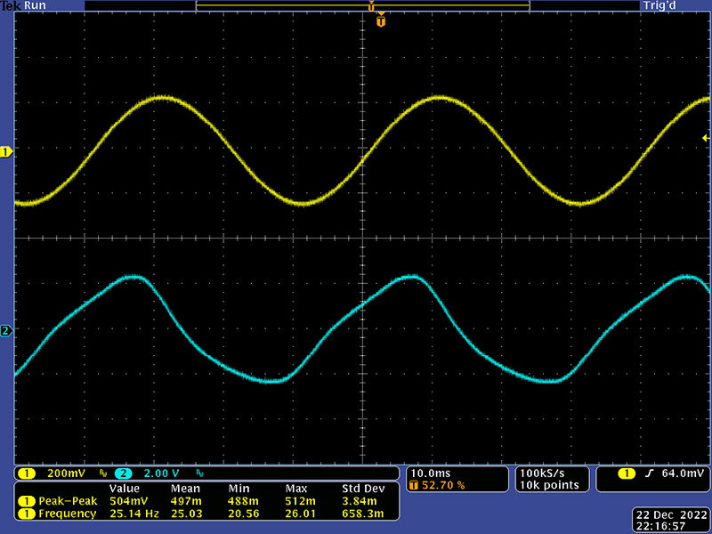
This scope image shows a 500 mV pk-pk 25 Hz input at which the locked oscillator shows distortion.
By 80 Hz the locked oscillator shows a nice sine wave.
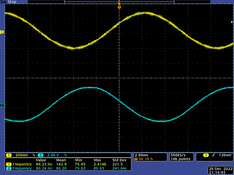
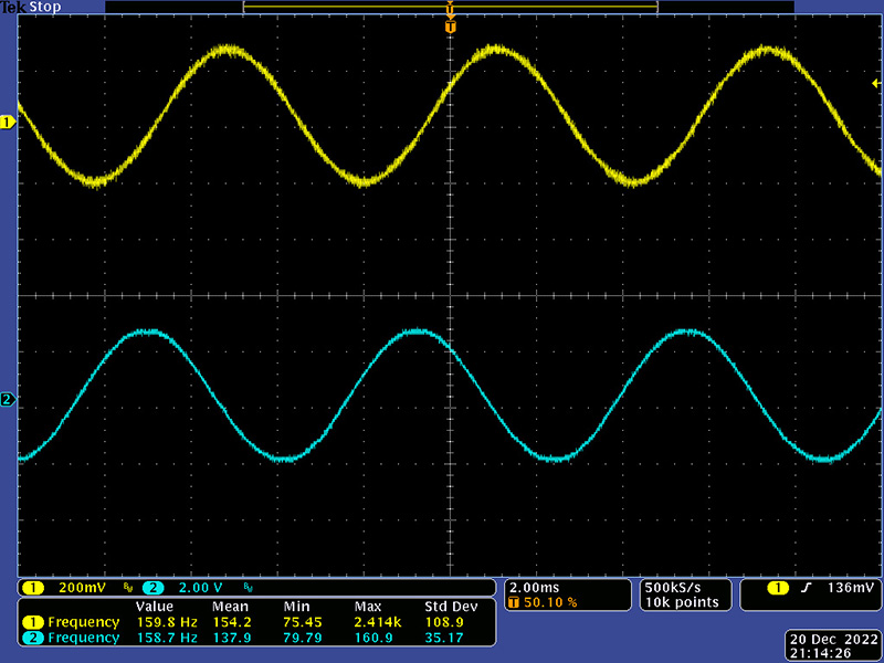
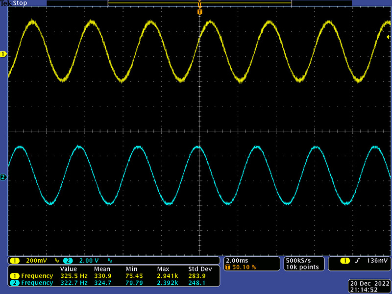
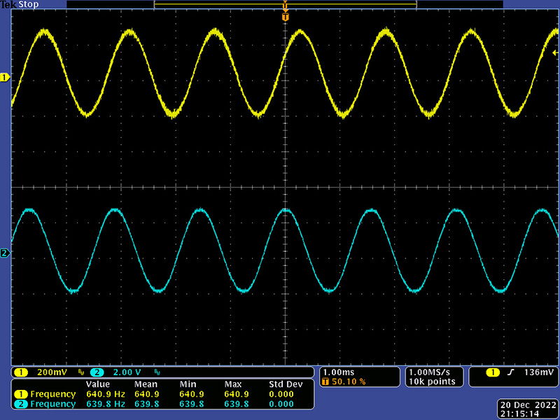
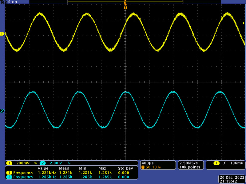
These next scope images show the input and locked oscillator at roughly 160 Hz, 320 Hz, 640 Hz, and 1280 Hz octaves.
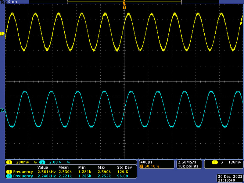
This scope image shows an unlocked oscillator at 2560 Hz input.
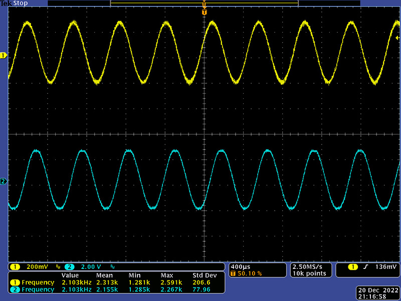
This scope image shows a maximum locked frequency of 2100 Hz.
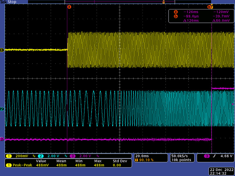
The 232 takes about 125 mS from an input signal to lock and generate the pulse.
The pulse is the typical trigger/gate with a trigger of 12V peak and 160 µS and a gate of 6.8V.
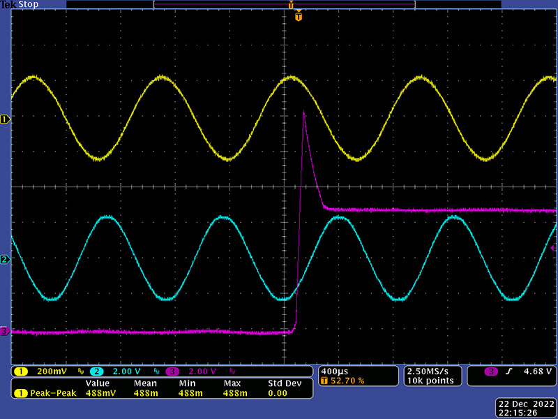
These next images show the operation of the Transfer Gate. This scope image shows the general following of the input envelope (magenta is the locked oscillator output).
![]()
Looking at the leading edge of the incoming envelope, you can see that the output is muted until the oscillator is locked.
![]()
The CV is not a constant V/Octave. It remains at -3.990V until about 130 Hz. It then scales roughly at 4V/Oct. The first V/Oct measured is likely low based on the frequency of 125 Hz being a bit below the minimum frequency.
| Frequency | Voltage | V/Octave |
| 125 Hz | -3.990 | |
| 250 Hz | -0.4607 | 3.529 |
| 500 Hz | 3.599 | 4.059 |
| 1000 Hz | 7.698 | 4.099 |
| 2000 Hz | 11.900 | 4.202 |
Here is another set of measurements starting at a higher frequency where the variation is 139 mV, or just over a semitone.
| Frequency | Voltage | V/Octave |
| 200 Hz | -1.700 | |
| 400 Hz | 2.295 | 3.995 |
| 800 Hz | 6.429 | 4.134 |
| 1600 Hz | 10.538 | 4.109 |
Operation
Since this module provides a tracking sine oscillator, I'm not sure that the CV output was intended to be accurate enough to drive other oscillators. It likely was more for general use for filters and other wave shaping modules.
This module runs on +/-15V and +24V but this one has been modified for simply +/-15V. There is one mod resistor which shifts the CV output more positive which makes it quickly run out of headroom operating on 15V. It has also been modified so the second CV jack is a different internal CV which was to be used with external circuitry for Mort Subotnick to provide a 1V/Oct CV.
In this video I am using a 258 VCO set to square as the input signal. The video starts with a frequency sweep over the usable frequency range of ~100 Hz to 2 KHz and the 232 tracks very well. I then drive the VCO with a keyboard so the frequency jumps between notes. You can hear occasional "whoops" as the locked oscillator takes a finite time to sweep and lock to the correct frequency. Lastly, I gate the keyboard so there is no input signal between notes. The locked oscillator output is patched to the Transfer Gate input. With no input signal, the locked oscillator drifts to a high frequency and the Transfer Gate mutes the output. This generates "whoops" on most notes as the locked oscillator takes finite time to sweep to the correct frequency.
The tracking filter circuitry uses vactrols and it may be that their responsiveness is the issue. In addition these vactrols are 50+ years old and my experience is they do change with time. The MEMS 232M with their new vactrols is more responsive.
It would be interesting to use this module to track an acoustic wind instrument to see how well it performs. When driving from a keyboard that generates a gate, one can use the keyboard gate with a slight delay to mute the "whoops". Also, a bit of portamento on the input signal improves the the ability of the locked oscillator to sweep to the correct frequency.