 |
140 Timing Pulse Generator Module |
|
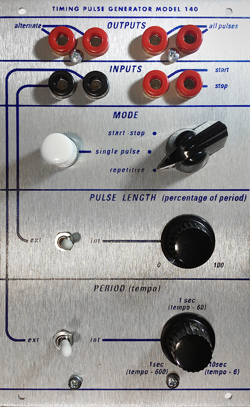
I helped an individual by email to debug their 140 Timing Pulse Generator. This is his reproduction 140 panel.
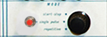
He sent me some photos of a vintage module. The 140 used various kinds of push buttons - white, red, and yellow as in this picture.
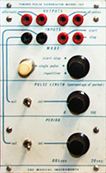
They also used a different style red and black switch as shown in this photo. The larger knobbed 140 had a longest period of 20 seconds. The smaller knobbed ones had a longest period of 10 seconds.
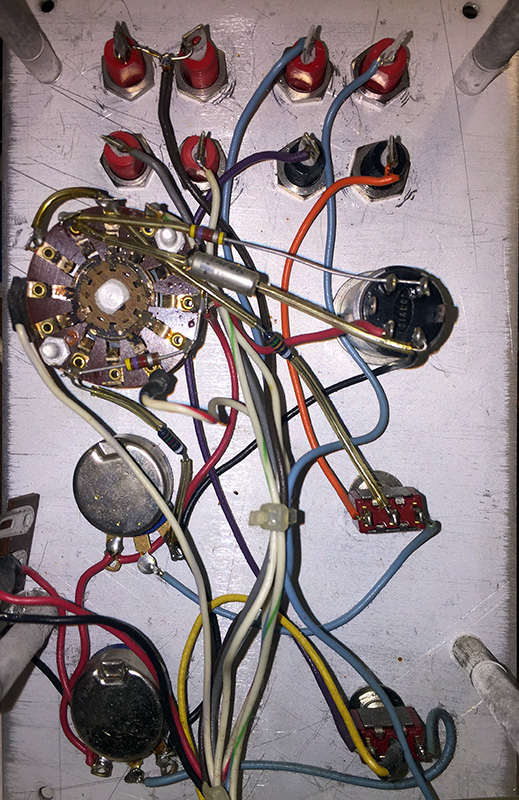
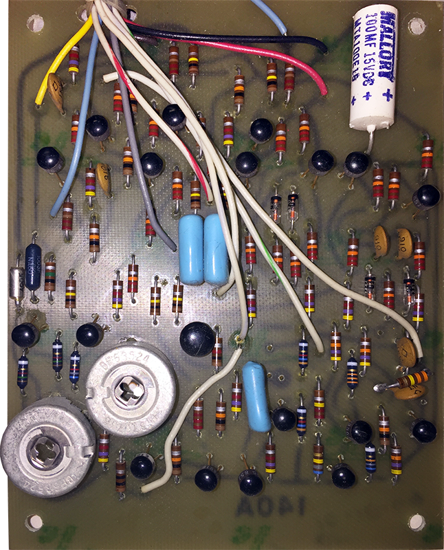
Here are some photos of the inside of the module. S2, S4, and S6 are part of the multi-wafer rotary Mode switch. S3 is the momentary Single pushbutton.
Circuit Description
I wrote-up this description to help debug this module by email.
Transistors Q1 through Q10 form the internal trigger generator with the output at the collector of Q10. The internal trigger is active high and is valid as long as the pushbutton is depressed. The minimum width is defined by the RC time constant of R174 and C4. This also debounces the pushbutton.
Q11 and Q12 are a /2 (divide by two) and will toggle states on every trigger. Q11 will be high and Q12 low, and then on the next internal trigger Q11 will be low and then Q12 will be high, and this cycle repeats on every internal trigger.
The Alternate Out circuits are simple two stage inverters with an AND input (the whole two transistor circuit can be thought of as a AND gate). The collector of Q16 is one output and is pulled high and floats low. It is pulled high when the base is driven lower than 14.3V. That will occur when Q15 is off as its pulldown resistor will turn on Q16. When Q15 is on the 14.7V Vce-sat is smaller than the bias so Q16 turns off. Q15 has three inputs: Start, /2, and the internal trigger. Start is pulled high by another 22K resistor that parallels R45 and R46 when the rotary switch is set to Single. The /2 will be high half the time as it alternates. The last input is the internal trigger. When all three inputs are high Q15 turns off which turns on Q16 and the Alternate Out. When the internal trigger goes low, it will turn on Q15 and turn off Q16 and the Alternate Out.
The second Alternate Out circuit consisting of Q17 and allow Q18 is similar except there is no Start input. On the next internal trigger, the /2 Q12 collector will go low thus keeping Q15 on and Q16 off. However, the Q11 collector will go high so when the internal trigger goes high it will now turn off Q17 and turn on Q18 for the second Alternate Out. Again, when the internal trigger goes low it will turn off Q18.
The collectors of Q15 and Q17 are also fed to Q19 for the All Pulse Out. It works in a similar fashion except on every internal trigger. When the internal trigger is high and either Q15 or Q17 is off, Q19 will turn on. When the internal trigger goes low, Q15 and Q19 will be on which turns Q19 off.
This is what happens when an analog engineer designs digital circuits. Certainly digital logic was available in this timeframe. The /2 and the Start and Stop circuitry could be done with simple flip-flops. The outputs could be done with simple buffers and logic gates. But, it works.