|
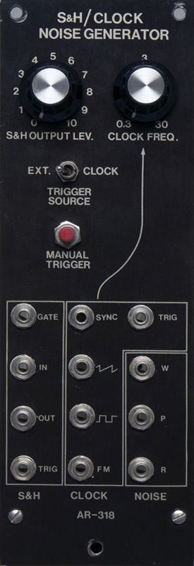
Aries
AR-318 |
|
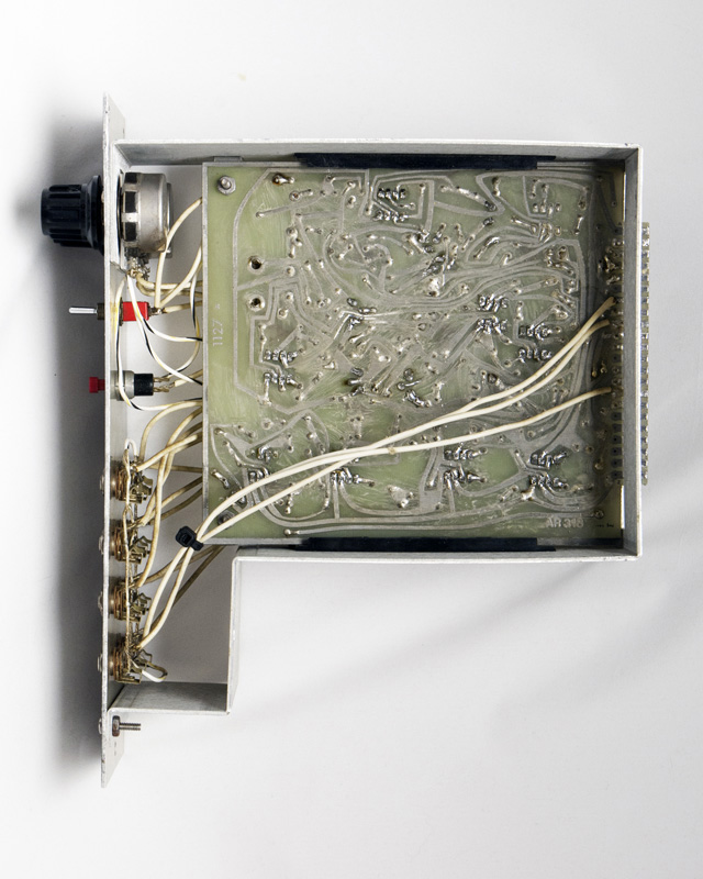
Aries modules were available both as kits and factory modules. This module sold in 1975 for $59.50 in kit or $119.00 assembled and raised slightly in 1977 to $71.00 in kit or $121.00 assembled. This module appear to be a kit due to the build and solder quality.
I combined specifications and schematics from Robert Leiner (with permission) and my photos into a PDF document.
AR-318 S&H-Clock-Noise Generator Document
Aries AR-318 Documentation (compliments of Michael Gilbert)
I have not been able to find PCB layout information. Some components are placed somewhat randomly on the PCB so tracing the circuit takes time. Access to the PCB component side is also challenging due to the number of front panel wires. The bottom PCB rail interfered with the mounting bracket which is another indication that this was most likely built as a kit.
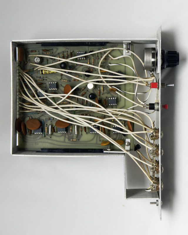
The PCB is a single sided tin with no solder mask. Care is required when doing repairs as the pads do lift easily.
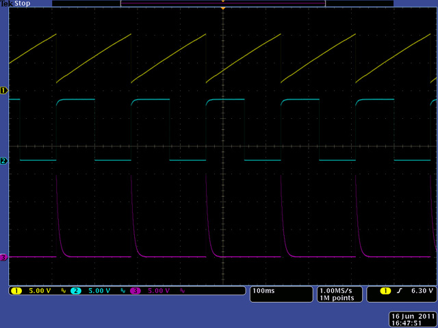
Here is a scope image of the three noise outputs. The white output is +/-10 volts while pink and random outputs are +/-7.5 volts. In this 10 sec sample you can see the slowly varying random output.
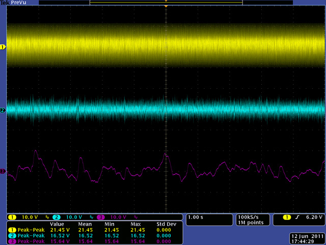
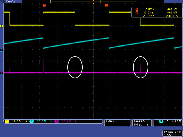
Here is a 1 sec sample where you can see the lower frequency random nature of the pink noise
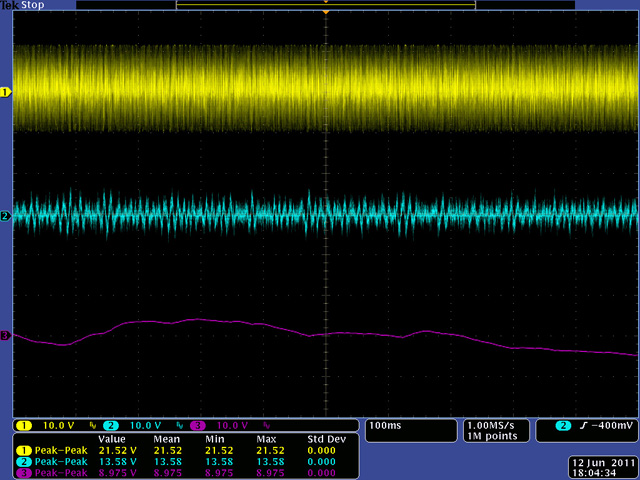
Here is a 1 mS sample where you can see the white noise RC wave shape due to the low pass nature of the circuit.
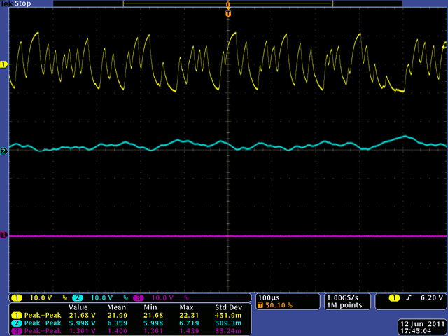
This scope image shows the three outputs from the Clock Generator. Note the square and ramp waveforms are 0 to 10V and the trigger output is the saturated output of an op amp so is 0 to 15 volts.
The timing capacitor was wrong so the maximum clock frequency was 45 Hz, 50% faster than the spec of 30 Hz. After replacing the timing capacitor I adjusted the frequency range centered around the specifications.
| Internal Clock Frequency | ||
| Measured | Specified | |
| Minimum | 0.2 Hz | 0.3 Hz |
| Maximum | 40 Hz | 30 Hz |
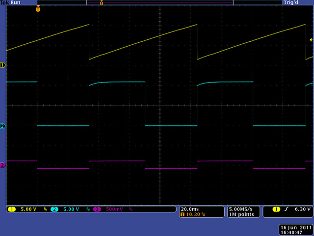
This image shows phantom triggers (magenta) on the falling edge of the square wave. The circuit uses a LM301 op-amp as a comparator on the ramp wave to generate the square wave and there are some oscillations as the ramp increases through 0V.
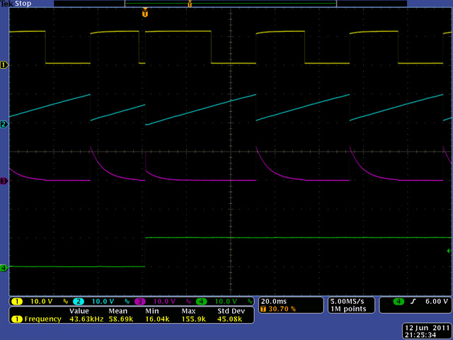
This scope image shows the sawtooth out (yellow), sample in (cyan), sample out (magenta) and trigger out (green). With both the sample in and out superimposed you can see the sampling on the falling edge of the sawtooth. I eliminated the phantom triggers by increasing C25 from 100 pF to 1000 pF.
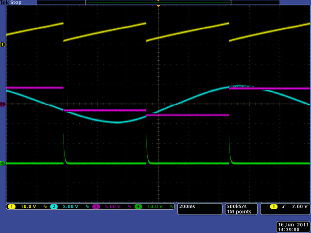
Increasing C25 eliminated the phantom triggers but there were still oscillations on the falling edge of the square wave. I decided to redesign the comparator properly with hysteresis. Simply lift pin 3 of U9 and connect a 6K8 resistor to ground and a 1M resistor to pin 6. That provided 200 mV of hysteresis as shown in the magenta trace. Problem solved - and I could have left C25 at 100 pF.
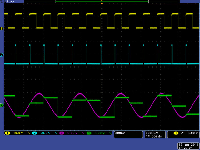
This scope image shows the sampling pulse to the FET (cyan). You can see how the sample output (green) follows the sample in (magenta) during the sampling pulse (e.g. tracking). The value of the sample in on the falling edge of the pulse is the value which is held.
This scope image shows the clock waveforms synchronized to an external 10V square wave.