|
DJB-SpeakJet PSIM Interface |
|
My first implementation of the SpeakJet was to interface the SpeakJet Rx input and Buffer Half Full signals to the PSIM J3 and use P7 as a serial output and P6 as a flow control input. This requires the use of the serial command which uses software-based timing. Accurate timing requires the interrupts to be disabled during the character transmission time of ~1 mS. MIDI inputs could be missed during this time and adding the appropriate enable and disable commands around individual character transfers is a programming hassle.
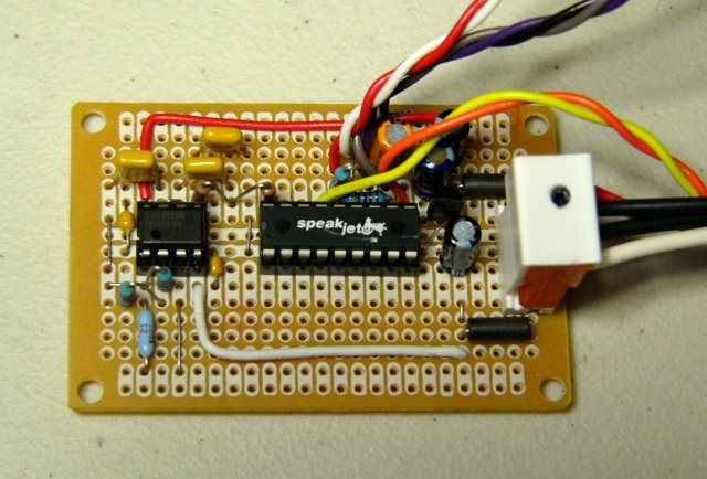
This photo shows my initial serial SpeakJet design with an active two pole filter and +5 volt regulator.
SpeakJet 2-pole filter and amplifier schematic
I2C Interface
I decided to use pins P6 and P7 for a synchronous interface which would not be impacted by interrupts. I chose I2C protocol and designed an I2C to serial bridge using an Atmel ATMEGA8 processor. This would interface the AtomPro P6 and P7 pins to the SpeakJet through I2C. Since it is a synchronous software implementation in the AtomPro, it is not impacted by interrupts.
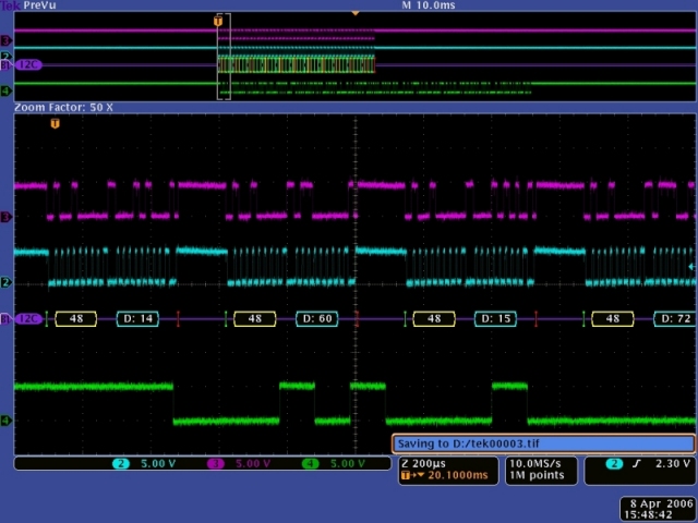
Here is a scope image of my I2C to serial bridge. Channel 3 (magenta) is SDA (data) and channel 2 (cyan) is SCL (clock). These are single byte data packets so each pair of transfers consists of the I2C address ($48) followed by data. Channel 4 (green) is the 9600 baud serial data from the bridge to the SpeakJet.
TTS256
I decided to add a TTS256 text to speech chip to improve the SpeakJet functionality. The TTS256 will translate the text to SpeakJet codes upon receipt of an end-of-line ($0d). No more data can be sent to the TTS256 until the SpeakJet has finished talking. This scope image shows the latency between the $0d being sent to the TTS256 (yellow) and the SpeakJet speaking output (green). I had to add 12 mS of delay from the transfer of my end-of-line line character before reading the status of the SpeakJet speaking output.
I2C and TTS256 interface schematic
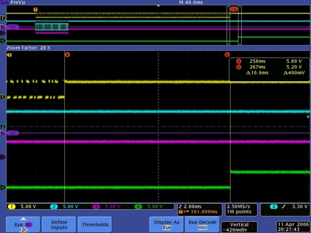
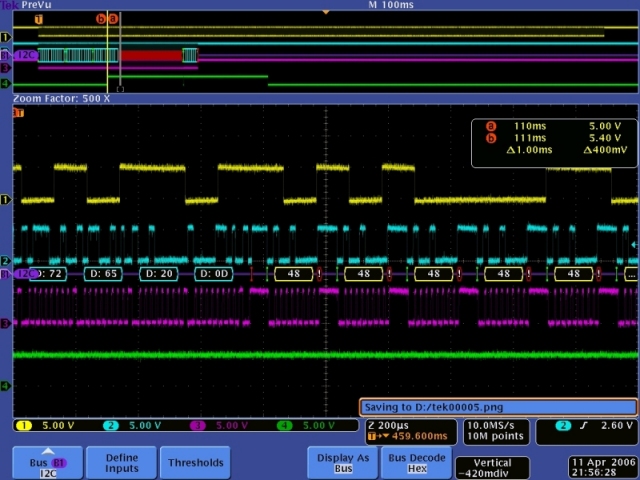
I implemented a three line (256 characters per line) buffer in my I2C bridge. While I doubt that this amount of buffering will ever be needed, I needed to implement flow control back to the PSIM. I chose to disable I2C acks when the buffer is greater than 511 bytes. The I2COUT command will goto the optional error label if there is an error such as not receiving an ack. I used this error label to re-execute the I2COUT command. However, this will cause the entire command to be sent again. To make this work correctly, I do not disable I2C acks until after a stop bit has been sent. This will synchronize the buffer with the retransmission of the I2C packet. Again, channels 2 and 3 show the I2C data. Channel 1 (yellow) shows the serial data transmission to the TTS256. Channel 4 (green) shows the buffer greater than 511 bytes. Nacks are show on the I2C bus as red. You can see the delay from the yellow cursor line (a & b) to the I2C nacks (red) which is the completion of the I2COUT data packet. Nacks continue until the green signals drops momentarily which causes another complete data packet to be transferred. Receipt of the first byte again takes the buffer greater than 511 bytes which the green signal indicates. It all works great.
The TTS256 will pass non-text characters through to the SpeakJet. This allows you to embed sound effects in with text. The two byte commands (volume, pitch, etc.) will only pass through correctly if the second byte is a non-text character. Otherwise the TTS256 will process the second byte as text and incorrect data will be sent to the SpeakJet.
These two byte commands can be sent to the SpeakJet by placing the TTS256 in pass through mode. This is accomplished by sending the text "passthruon" and an end-of-line. All characters sent to the TTS256 will be sent directly to the SpeakJet. An "X" ($58) will terminate the pass through mode. Note that this character cannot be used as the second byte of a two byte command as it will terminate the pass through mode. An "X" is also used to terminate the SCP mode for communication directly with the SpeakJet internal registers. An alternate \A may be used to terminate SCP mode and not pass through.
Construction
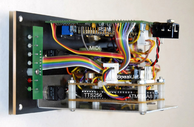
I built the I2C bridge and TTS256 on a separate daughterboard which mounts below the SpeakJet board. Here's a photo of my PSIM with the additional daughterboard making a very tight module.