|
Serge Modular
Rebuild |
|
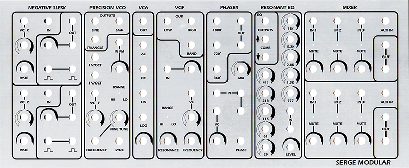
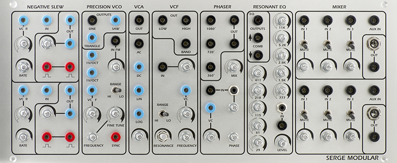
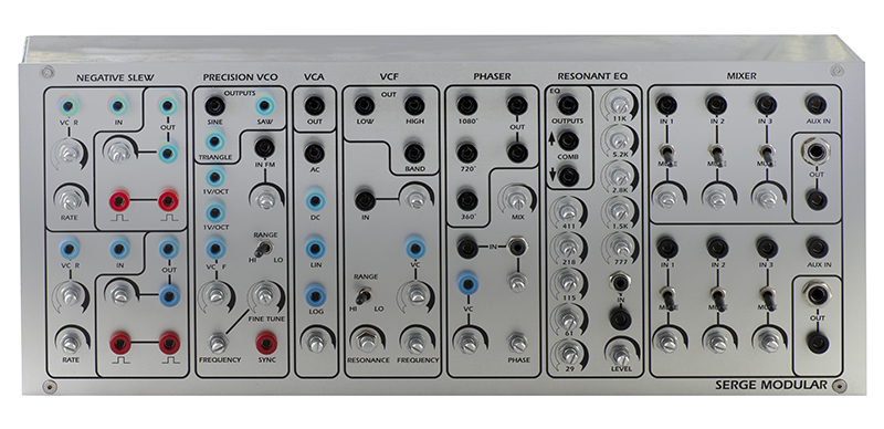
Box 3 consists of a R9 Negative Slew, 106B Precision VCO, R6 Gate (VCA), R12 VCF, 2565 VC Phaser, 202 Resonant EQ, and a AMX 229 Dual Mixer.
R9 Dual Negative Slew
Details on Box 1 page.
106B NTO VCO
Details on Box 1 page.
R6 Gate (VCA)
Details on Box 1 page.
R12 Voltage Controlled Filter
Details on Box 2 page.
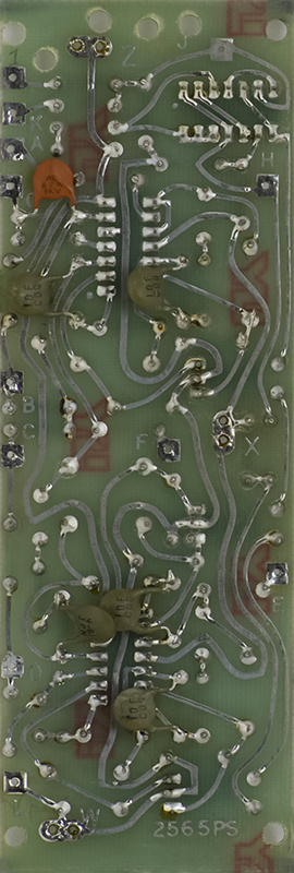
2565 PS Phaser
This description of the 2565 VC Phaser (PHA) is from the 1979 catalog. "The VC Phaser is perhaps the lowest noise and lowest distortion phase shifter available today. As an aid to recreating some of the subtle properties of phase delay in acoustic sounds, three separate outputs are provided with 360 degree, 720 degree, and 1080 degree of voltage controllable phase shift. A Mix output combines the 1080 degree phase shift with the input signal to produce the multiple notch filter effect that is usually associated with phase shifters. The VC Phaser's log-conforming characteristics and the manual and voltage controls enable ultra-smooth, precisely centered sweeps of phase shift for both spatial effects and timbral modification."
The banana jack is normalled through the 3.5mm jack and an input attenuator has been added.
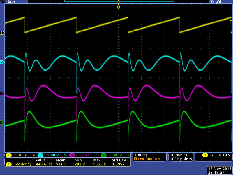
Here are some scope images of a ramp input (yellow) and the 1080° (cyan), 720° (magenta), and 360° (green) outputs with the Phase control full CCW. The high frequency components of the ramp wave add nicely to the output.
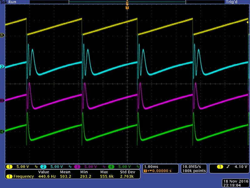
Here is the same setup with the Phase control set to mid.
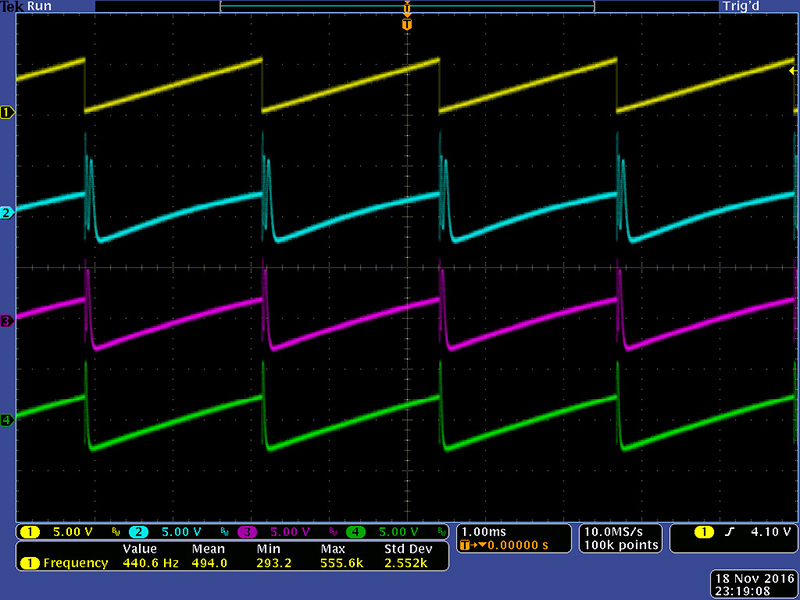
Here is the same setup with the Phase control set to full CW.
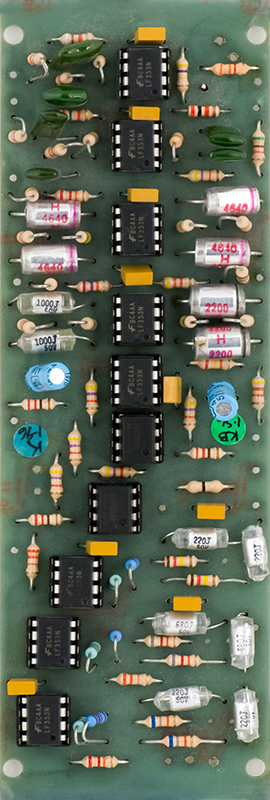
202 Resonant EQ
This description of the 202 Resonant Eq is from the 1982 catalog. "The Resonant Equalizer is a unique ten-band filter designed specifically for electronic sound synthesis and processing. Except for the top and bottom frequency bands, all other bands are spaced at an interval of a major seventh. This non-standard spacing avoids the very common effect of an accentuated resonance in one key, as will be the effect from graphic equalizers with octave or third-octave spacing between bands. Spacing by octaves will reinforce a regular overtone structure for one musical key, thereby producing regularly spaced formants accenting a particular tonality. The Resonant Equalizer's band spacing are much more interesting, producing formant peaks and valleys that are similar to those in acoustic instrument sounds.
There are three equalized outputs, two which mix the alternate filter bands, and one which is a mix of all filter bands. The upper comb output lets pass the frequency bands at 61 Hz, 218 Hz, 777 Hz, 2.8 kHz, and 11 kHz. The lower comb output mixes the other bands (29 Hz, 115 Hz, 411 Hz, 1.5 kHz, 5.2 kHz). This equalizer is different from other equalizers in that the bands can be set to be resonant. When the knobs are in the middle position, the response at the main EQ Output is flat. When the knobs are positioned between the 9 and 3 o'clock position, up to 12 db of boost or cut is set at the band. If the knob is set beyond the 3 o'clock position, the band will become resonant, simulating the natural resonance of acoustic instrument formant structures. Below the 9 o'clock position, increased band rejection is achieved."
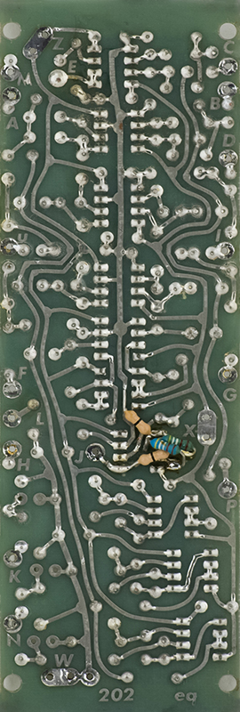
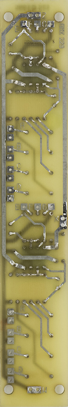
The banana jack input is normalled through the 3.5mm jack. After powering on, I determined that the resistor modifications on the rear of the board needed to be removed. I'm not exactly sure what they were trying to do but it didn't work.
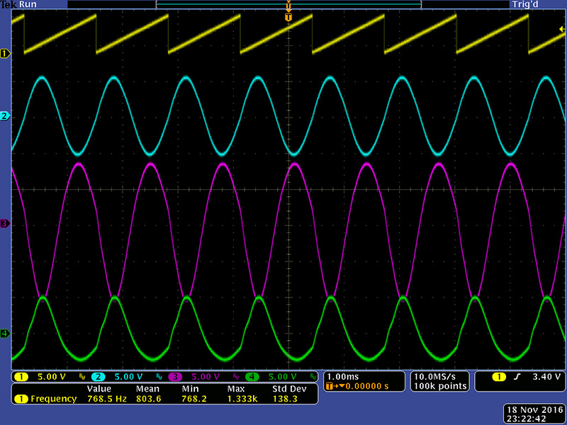
Here are some scope images of a 768 HZ ramp input (yellow) and the Eq (cyan), Comb Up (magenta), and Comb Down (green) outputs with only the 777 Hz control CW and all other controls CCW. There is significant gain through this module so the input attenuation control is very useful.
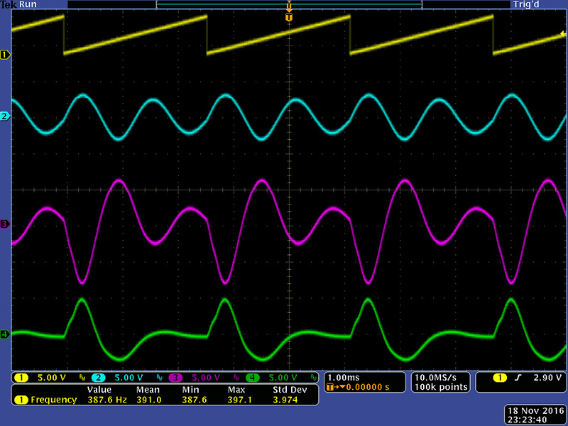
Here is the same setup with the input ramp lowered to 387 Hz. The output waveforms have some very nice artifacts.
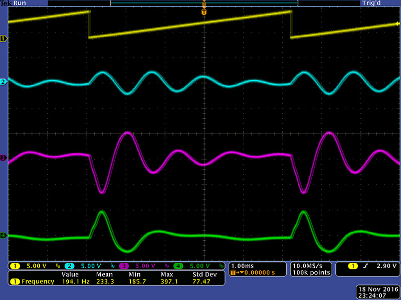
Here is the same setup with the input lowered to 194 Hz.
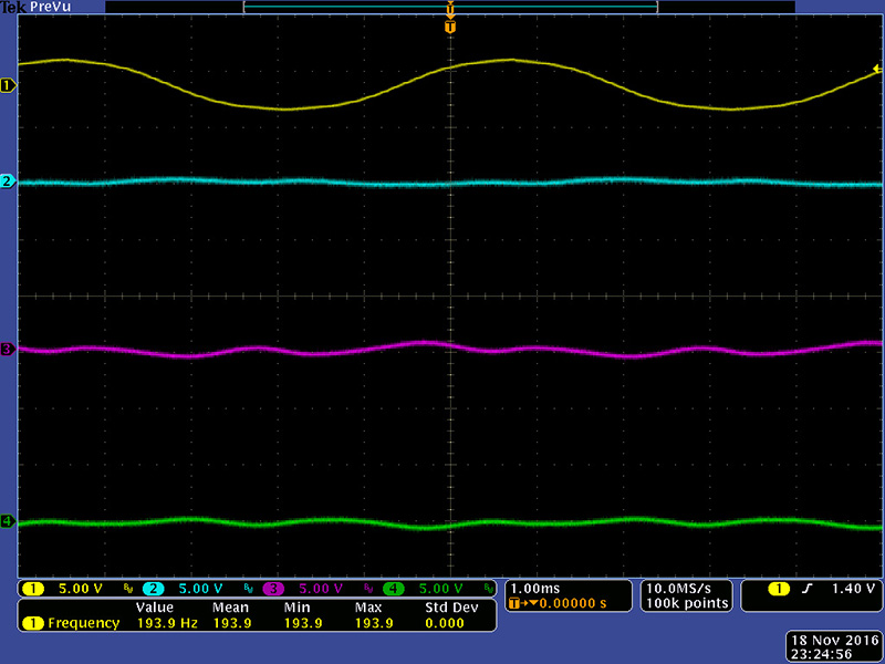
Just to demonstrate the output artifacts are coming from the high frequency components of the ramp waveform, here is the same setup with the input waveform changed to a sine All outputs are near 0 which they should be..
AMX 229 Dual Mixer
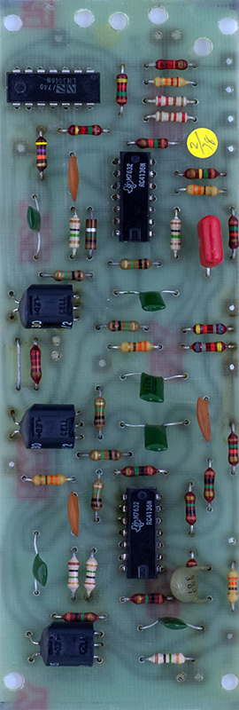
The AMX 229 appears to be an upgrade of the original R2 mixer which has 4 non-inverting inputs and two inverting inputs.. It was designed to accommodate capacitor coupling on the non-inverting inputs which have been jumpered with 0 ohm resistors (single black stripe). There are also 0 ohm resistors from the positive input of the op-amp to ground. The non-attenuated input is to cascade multiple mixers.
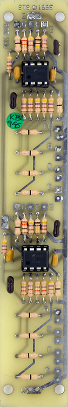
Construction
Two bus bars mounted on rear brackets holds all the PCBs which hinge on the bottom. The potentiometers have to be mounted diagonally for clearance. Three of the jacks are 1/4" and two are 3.5mm. The power is daisy chained between all the modules except for the VCs which has a dedicated power cable. The twists in the power wires is to allow slack for the PCB to be rotated up.
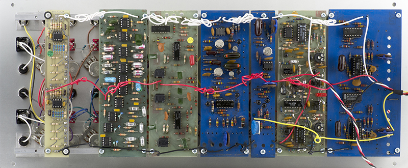
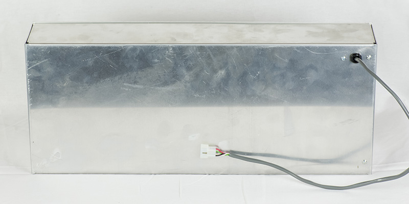
The box is quite clean with only 4 panel screws in the front.
The rear just has the Serge 4 pin connector for power.