|
Klinkenberg Triple
Sequential |
|
I have a 208 Triple Sequencer card as described on the Triple Sequential Voltage Source for the Buchla 208 thread on the ModWiggler forum. This card is almost all SMT, and as Ron describes, is really a challenging build. It is loosely inspired by the 123 Sequential Voltage Source and adds a lot of capability to the 208. The leftmost control for each sequencer sets the number of stages for that sequencer and there is an additional slew control for the output.
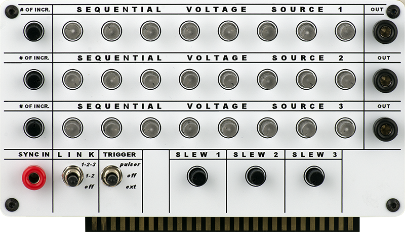
There are multiple modes for the operating the card. 1-2-3 links the three sequencers together and the sequence length is controlled by the top sequencer control. 1-2 is similar for linking the top two sequencers while allowing the third to operate with an independent length. Off allows all three sequencers to operate with an independent length.
Pulser mode triggers the sequencers from the 208 Pulser when the 208 is in Both mode. However, a card jumper allows some additional flexibility. If the 208 Pulser is off with the period slider at minimum (top), and the card is set to Pulser mode, a Sync In pulse will advance the sequencers and generate a Pulser output. If the 208 Pulser is off with the period slider at minimum (top), and the card mode is set to Off, a Sync In pulse will generate a Pulser output but not advance the sequencers. If the card is set to Ext, a Sync In pulse will advance the sequencers with no effect on the Pulser.
The illuminated shaft potentiometers look quite nice when operating.
Construction
The LEDs on PCB1 are soldered first with the potentiometers covering them. They have an orientation dot so care must be taken to get them all oriented correctly.
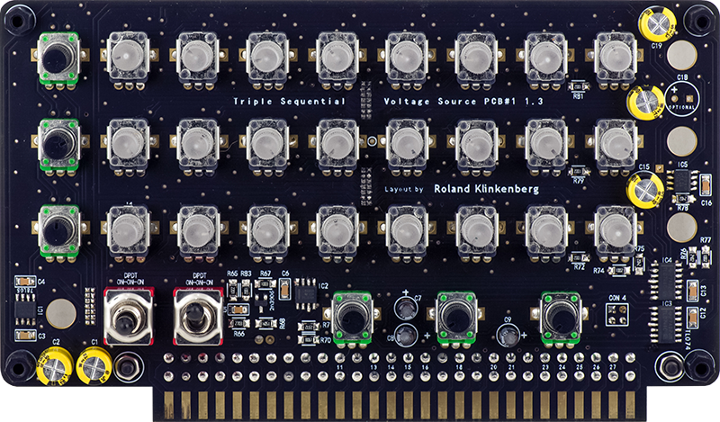
I assembled the complete PCB except the interconnect pins to the panel and PCB2. I soldered the female connectors on those PCBs first, being very careful to place them accurately. Then I installed the pins in those connectors and assembled each half to make sure the pins aligned with PCB1 before soldering.
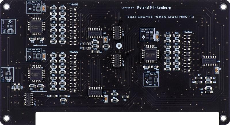
PCB2 only has components mounted on the front. The rear is covered by a decorative white PCB.