|
216 Touch
Controlled |
|
I built a 216 Touch Controlled Voltage Source module for someone else. They sent me a complete kit of parts and I assembled and tested the module. Many of the components are sourced through Mouser but specialized parts, panel, and knobs have specific sourcing requirements.
I made reference designators from the PCB images. The components cover the silk screen legends once populated which makes it hard to debug if anything is wrong.
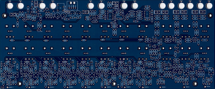
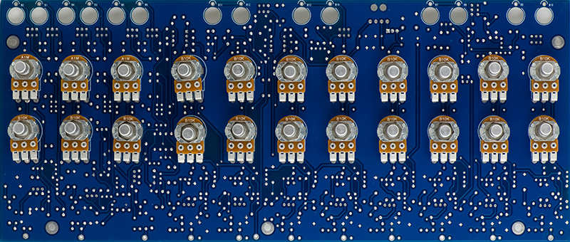
PCB Front Reference Designators
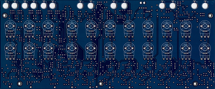
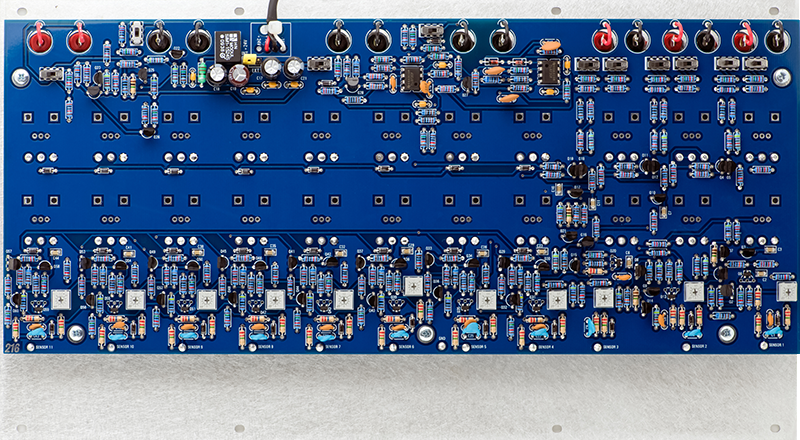
PCB Rear Reference Designators
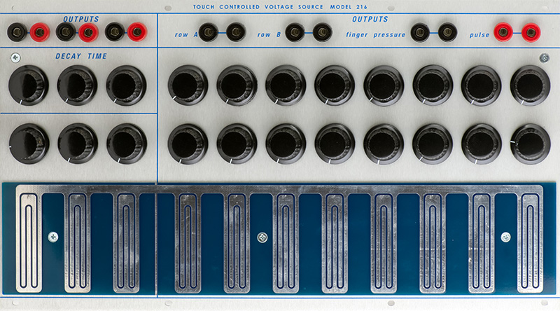
The front panel consists of 22 potentiometers and the touch panels. These potentiometers have only one pin soldered. I mount the panel then reflow the pin so the potentiometer relaxes without stress, then solder the other two pins. There was a bit of a bow in this PCB so the potentiometers in the middle sit a bit further off the PCB.
There are quite a few components on the rear of the PCB.
Construction
Construction was not difficult. I countersink the three holes in the sensor PCB so I could use flat head screws. I used Krylon Acrylic Crystal Clear flat to clear coat the keys. I put about 10 coats on the keys before I installed them and it really looks nice.

Calibration of sensors 1 - 3 is quite easy as you adjust the trimmers for 0V output. You set the voltage high and then decrease it until you reach 0 volts.
Calibration of sensors 4 - 10 is critical because set too high the sensor will not release when the next sensor is pressed. Trimming is a bit difficult as the sensor and trimmer are on opposite sides so access to both is a challenge. There are lots of suggestions for trimming by measuring voltages but I found it is best to start low and trim until the key turns on with no finger, and then back it off a bit. Then check to make sure each key works well and the levels maintain. Make minor adjustments if necessary.
The switches adjust the voltage levels between 5V and 15V except for Pressure which only reaches 10V.
|
216 Switch Functions |
|||
|
Switch Postion |
|||
| Switch | Function | Stripe | Blank |
| SW1 | Sensor 1 Pressure | 5V | 15V |
| SW2 | Sensor 1 Voltage | 5V | 15V |
| SW3 | Sensor 2 Pressure | 5V | 15V |
| SW4 | Sensor 2 Voltage | 5V | 15V |
| SW5 | Sensor 3 Pressure | 5V | 15V |
| SW6 | Sensor 3 Voltage | 5V | 15V |
| SW7 | Sensors 4-11 Pressure Voltage | 5V | 10V |
| SW8 | Sensors 4-11 Pulse Voltage | 5V | 15V |
| SW9 | Sensors 4-11 Row A Voltage | 5V | 15V |
| SW10 | Sensors 4-11 Row B Voltage | 5V | 15V |
Operation
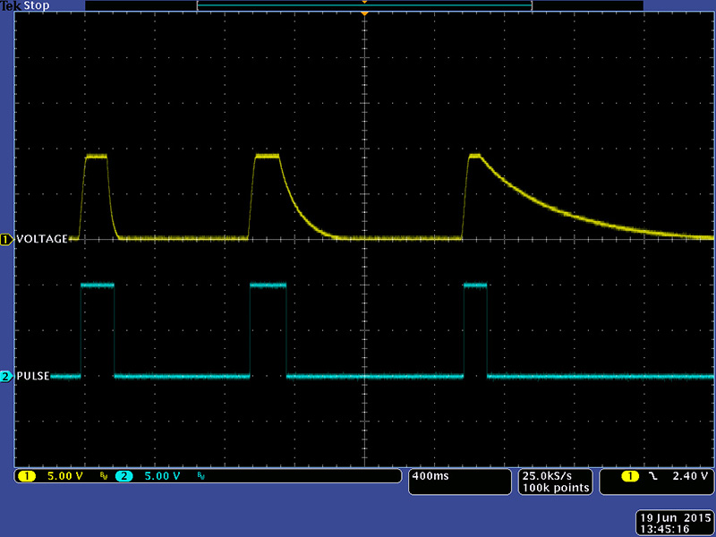
The 216 is comprised of two separate sections. The first three touch sensors provide a voltage output with a variable baseline and decay time and a pulse (gate) output. This scope image shows three different decay times.
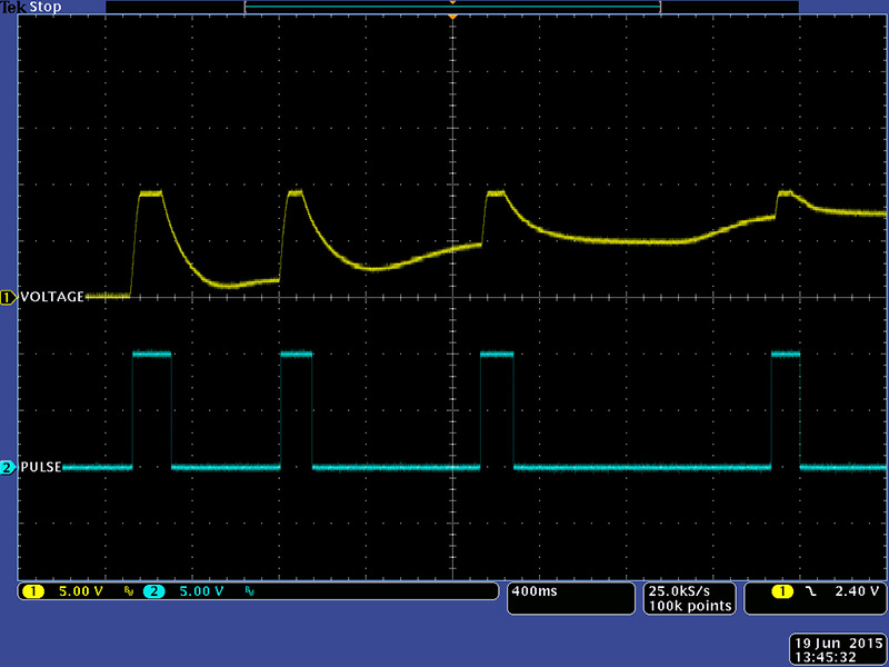
In this scope image I am adjusting the lower unmarked control which sets the baseline for the voltage output. After the decay I am adjusting the control to a higher baseline. The voltage out amplitude is always the same.
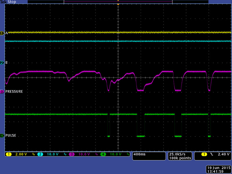
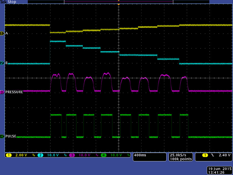
The second section is sensors 3 - 10 which provide a latched A voltage output, latched B voltage output, pressure, and pulse (gate). The top control sets the A output voltage and the bottom control sets the B output voltage. These voltages are held until the next sensor is pressed. This scope image shows a finger "slide" from sensor 3 to sensor 10. The A row is adjusted for 1V/Oct semitones.
The pressure sensitivity has a very narrow range. You can trigger the sensors with little pressure and full pressure but more difficult to get subtle variations in between. This scope image shows a small variation in pressure.
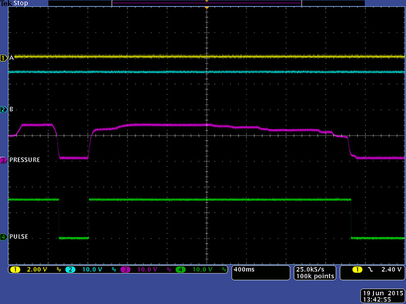
When you release a sensor the pressure and pulse pulse outputs go false so it is easy to get multiple triggers with very light pressure as shown in this scope image.