 |
Synthesis Technology |
|
This page details modifications I made to my MOTM modules.
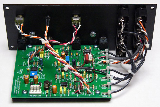
MOTM-101
Replaced D1 & D2 with a transistor emitter-collector junction. I sorted through my transistors until I found one that generated excellent noise.
Replaced R7 with a 10K trimmer to adjust the Pink output to 10 volt pk-pk.
Replaced R11 with 27K for 10 volt pk-pk on Slow output.
Replaced R25 with 9K and C24 with 100 nF for 1.0 mS sample strobe.
Added separate random output by adding another LF398A on top of the existing LF398A, wiring the input to the pink source, and buffering the output with the spare U3B op amp. Mounted the new Random jack on the front panel.
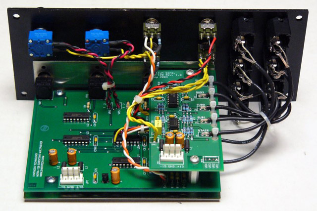
MOTM-120
Installed a Tellun 120R PCB with a Stooge panel to add staircase and individual sub-octave outputs.
Added 100 pF capacitors across pins 1 and 2 of U7 and U8 to eliminate crosstalk from the B input when in sub mode.
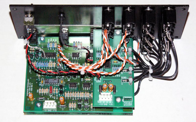
MOTM-320
Installed a Tellun 320R PCB with a Stooge panel to add inverted outputs, shape cv control, and range switch.
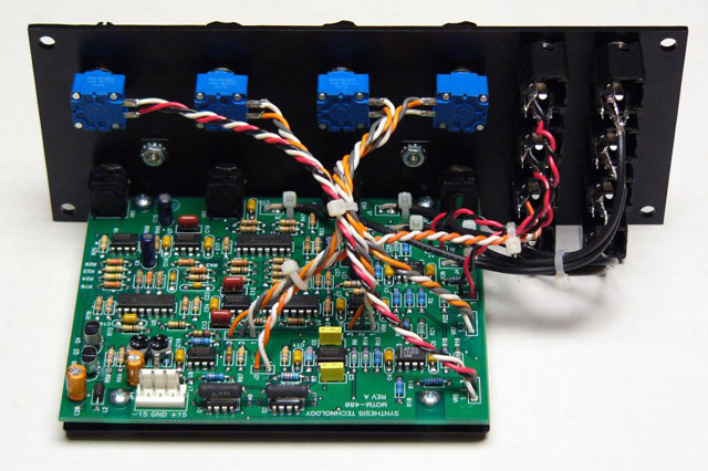
MOTM-480
Replaced R56 and R61 with 1K trimmers. The trimmers fit in the resistor footprint by clipping one lead and slightly spreading the other two leads.
I had very weird distortion and strange modes at high resonance levels. You can hear the distortion as well as a mode that filter seems to 'snap' in or out of. Decreasing the input level to '8' eliminated both effects but I wanted to avoid them at both maximum input level and resonance. I adjusted the maximum resonance to limit the maximum output voltage to +/-13 volts.
Here are some samples of
increasing resonance and
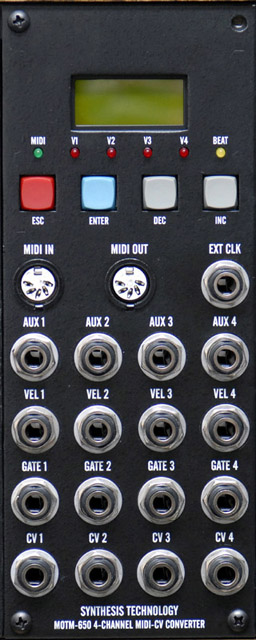
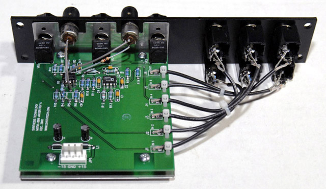
MOTM-650
Replaced those oversized 1/4" jack washers with cad-plated washers that fit proper and look much better. The washers dimensions are 0.656 inches outside diameter, 0.470 inches inside diameter, and 0.030 inches thick.
MOTM-730
I evaluated the prototype MOTM-730 and my summary is here.
MOTM-800
I modified two modules to operate with a trigger delayed from gate. Details are on my DJB-008 page.
MOTM-830
I modified gain to unity for In-1 to In-5 by changing R8 and R17 from 44.2K to 100K and R18 from 100K to 49.9K
I modified In-6 gain to 3X by changing R9 to 33K.
MOTM-850
My Yamaha pedal was 36K instead of 50K so I changed R17 to 33K and R18 to 39K.
I limited the gate output to +5 volts by adding a 620R resistor across the output jack.
I modified two different MOTM-890 modules
I modified for unity gain by changing R13 to 10K and R12 to 2K5.
I replaced IN-2 and IN-4 with frequency mixer using the Tellun MUUB-4 pcb.
Variable high gain
I added a variable high-gain amplifier for IN-2 and IN-4 (gain=4x to 30x).
I added two tiny knob (Mouser 506-PKG40B1/8) gain controls on the front panel.
I modified IN-5 for 3X gain by changing R8 to 300K and R17 to 75K.
I modified for unity gain by changing R13 to 10K and R12 to 2K5.
MOTM-900
I added a green Lumex LED as a power indicator. I used an MTA header to connect to a power connector.
MOTM E340 Cloud Generator
I bought the DIY kit and made a 5U module.
MOTM E350 Morphing Terrarium
I bought the DIY kit and made a 5U module.
MOTM E560 Deflector Shield
I bought the DIY kit and made a 5U module.
MOTM E580 Sampling Mini-Delay
I bought the DIY kit and made a 5U module.
MOTM E950 Circuit Bent VCO
I bought the DIY kit and made a 5U module.