|
Electronic Repairs and Restorations |
|
![]() 70's/80's
Dynaco Stereo
70's/80's
Dynaco Stereo
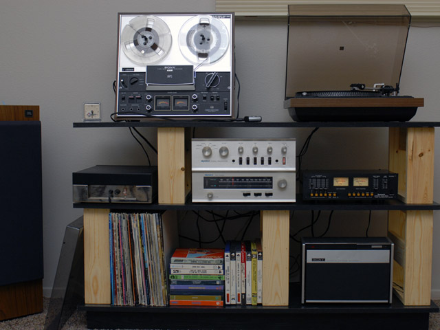
I've restored a set of 70's-80's stereo equipment. I bought the Sony TC-8 new (lower right) and a Sony TC-366 in 1970 which I later upgraded to this TC-377.
| Equipment | Date | Original Price |
| Sony TC-8 Eight Track Recorder | 1969 | $129.50 |
| Sony TC-377 Reel-Reel | 1972-77 | $420.00 |
| Dual 1242 Turntable / Shure V15 TypeII | 1978 | $225.00 |
| Dynaco PAT-4 Preamplifier | 1967 | $89.95 kit / $129.95 assembled |
| Dynaco FM-5 FM Tuner | 1971 | $199.00 kit / $319.00 assembled |
| Dynaco ST-120 Stereo Amplifier | 1966 | $159.95 kit / $199.95 assembled |
| Numark TC4100 Tape Mixer | 1985 |
$99.00 |
| JBL L60T Speakers | 1985 |
$265.00 each |
|
Total $1852.40 (in kit form) |
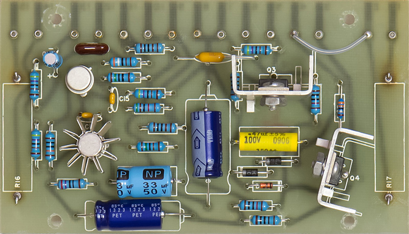
The Dynaco ST-120 had shorted output transistors so I chose to rebuild the amplifier PCBs. I upgraded the 7 watt resistors to 10 watts and increased R3 to 51K to compensate for lower beta transistors. The lower right heat sink is quite close to the screw so I reversed the screws so the head is on the PCB side. The nut is very close to the heat sink mounting nuts but it fits.
Dynaco ST-120 Amplifier Mouser Part Numbers
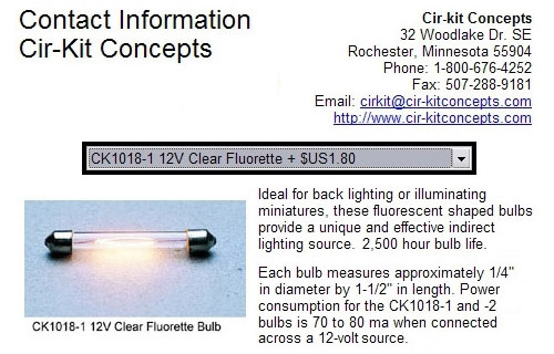
Dynaco FM-5 Tuner Replacement Lamps
The Dynaco FM-5 tuner that had one lamp burned out. All of the replacement information I found on the web indicated that replacement lamps are not available. Well, I found some! They are 12 volt fluorette lamps and I have found them at several doll house suppliers. My one good original lamp measured 140 mA and these replacements are 80 mA but appear just as bright. I bought the clear CK1018-1 clear lamps and my ends caps were straight instead of the conical end caps as shown in the photo. The overall bulb is the same size and fits perfectly.
Dual 1242 Turntable Adjustments
It took me a while to figure out how to adjust the turntable set-down for 7" and 12" records. The adjustment is under the Dual label on the right front. The logo snaps out of an adjustment hole and rotates clockwise. There is an index pin in the upper right side of the logo. There are two adjustment screws, one for each speed / size. The 'trick' is the opposite adjustment screw is in position. When the speed is 33 rpm, the 45 rpm adjustment screw is in position. You need to change the speed to 45 rpm, adjust the screw, change the speed back to 33 rpm, and try the set-down. The opposite procedure is used to adjust the screw for 45 rpm.
It also took me a while to figure out how to remove the turntable from the base. First, remove both screws holding the cable plate from the bottom. Then loosen each of the three mounting lockdown screws. With these screws loose, you can lift the turntable and angle the screw so the disc on the end clears the mounting slot. You have to do each of the screws separately.
The anti-skating control has three scales on it. The top upper scale has a horizontal ellipse indicating adjustment for an elliptical stylus. Below that is a scale with a small circle indicating the adjustment for a conical stylus. On the bottom is a scale labeled CD4 indicating adjustment for the special four channel stylus.
![]() 70's/80's
Marantz Stereo
70's/80's
Marantz Stereo
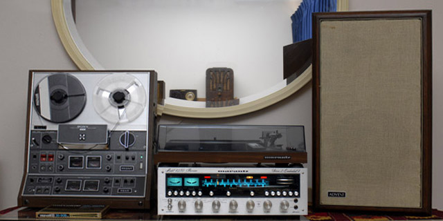
I've also restored this set of 70's-80's quad stereo equipment.
| Equipment | Date | Original Price |
| Sony TC-366-4 Quadradial Tape Deck | 1971 | $479.95 |
| Marantz 6150 Turntable / ADC QLM36 MkIII | 1977-79 | $180.00 |
| Marantz 4230 Quad Receiver | 1973-78 | $550.00 |
| Advent speakers | 1971 | $116.00 each |
| Total $1441.95 |
Marantz 6150 Turntable Repair
The Marantz 6150 turntable uses a direct-drive servo motor which pulsed at 33-1/3 RPM and was too fast at 45 RPM. I removed the rear cover of the servo motor exposing the control PCB. There are ~10 square pins you need to unsolder to remove the control PCB. There are two tantalum capacitors and five electrolytic capacitors plus a handful of other parts on the control PCB. I replaced all capacitors although I probably just had to replace the tantalum capacitors as I think they are the timing capacitors for the controller IC. The tantalum capacitor values are 0.68 µF and 1.0 µF. The electrolytic capacitor values are 4.7 µF (qty 3), 47 µF and 100 µF. Capacitor polarity is silk screened on the PCB making the repairs easy. Sorry, no pictures.
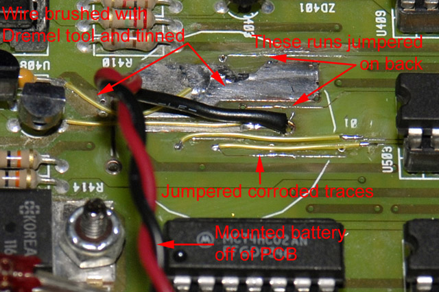
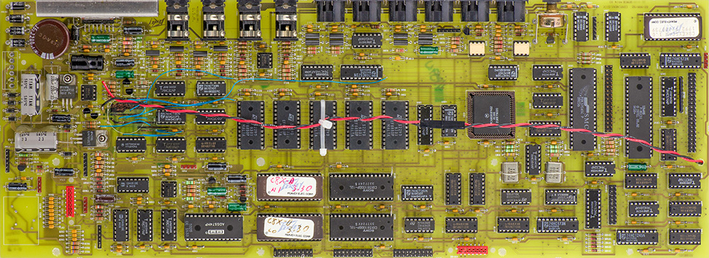
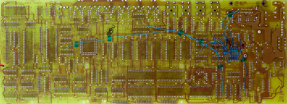
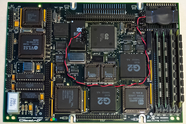
The NiCd battery in the DPM C8 is know to leak and damage the motherboard. My DPM C8 was still functional but I decided to pull the bottom panel and examine the battery. It had corroded and there was damage to the PCB Some of the leakage had dripped to the metal cover and started corrosion there as well.
I removed the battery and tried to clean up the traces. The copper had corroded quite badly and I didn't want to just leave it for fear that it would continue to corrode. I used a small wire brush and a Dremel tool to clean the traces down to copper. I tinned the exposed copper and the large areas were fine but the small traces were too damaged. I jumpered each of the five traces with wire and also the battery power traces since the vias were most likely damaged.
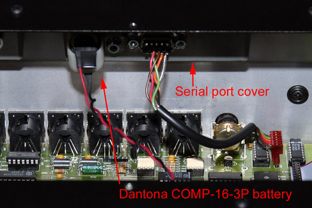
I replaced the battery with a Dantona COMP-16-3P nickel metal hydride. It was the same form factor for mounting on the PCB but I moved it to the rear of the serial port cover. The unit powered up and the display was mostly correct except the preset names were all smiley faces. Holding '0' and 'Enter' keys depressed while powering on initialized the non-volatile memory correctly.
Peavey will supply the schematics on discontinued products if requested. The set I received only covers the motherboard and one of the front panel switch boards. I've created a drawing of the cable connections to the motherboard.
* * * Do not ask me to repair one of these boards.
They can take up to 8 hours of very tedious work and
you never know if it will be a success. Peavey was right when they said
they were unrepairable. * * *
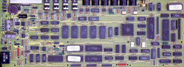
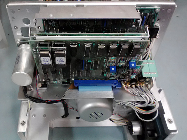
I've repaired a couple of these successfully, and failed at others. They are not fun and are very tedious. I have seen boards where the vias are corroded 6 inches away from the battery. The caustic leakage seems to follow the solder mask and then attack unmasked vias. These two images show the number of wires I have had to put on the PCBs. I drill out the bad vias and route the wire through the holes. That way I can tell if I have patched that particular trace.
Alesis Quadraverb-Plus Repair
My Alesis Quadraverb stopped working and was displaying garbage characters on the LCD. I assumed it was an intermittent connection and reseated all the ICs and cables with no affect. I found that reinitializing memory corrected the problem. The 3.6 volt lithium battery was dead and it seems the Quadraverb requires battery-backed memory to be valid for correct operation. Replacing the battery and performing a memory initialization corrected the problem.
Here are the various functions that can be accessed by key combinations:
| Key Combinations | Operation |
| Software version | Press both Page buttons (mine is version 2.02). |
| Memory initialization | Hold the Prog and Bypass buttons while powering on. |
| Internal diagnostics | Hold the Config, Pitch and Bypass buttons while powering on. You need to connect midi cable from In to Out for MIDI test. |
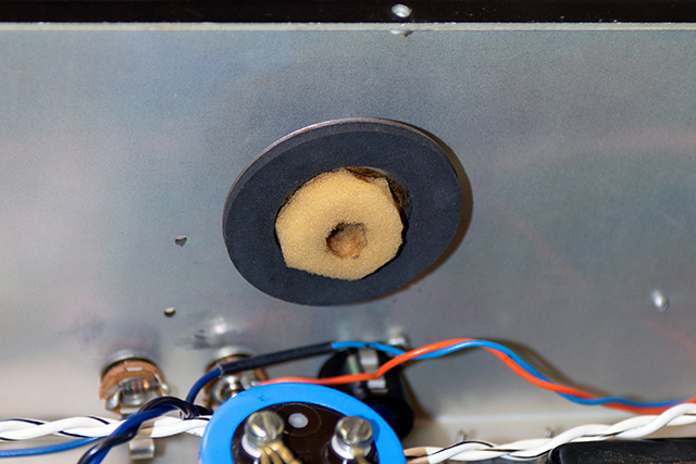
Sunken Speaker Repair
I had four Sunn 10 inch speakers that were very inefficient. I believe these speakers date from the mid 70's and have paper surrounds. Upon inspection I found that the cones have sunk inwards. In their normal at-rest position they are almost at the bottom of their travel range so they have very little compliance inwards (and hence very little volume). I've seen postings on the web for speakers that had sunk in and one site described a repair by moistening the surrounds and holding the cone outward until dry. I tried it and it worked! I experimented with different methods of holding the cone outwards. I tried foam between the frame and cone but this tended to deform the cone. I settled on using two small wood levers with an angled end to fit flush against the cone where the spider connects. I pried the levers against the frame to hold the cone outwards until the surround was parallel to the front of the speaker. I sprayed water on the paper surrounds and used a small brush to spread it to thoroughly soak the paper. When the surrounds dried the cone remained in this position. I have no idea why the speakers developed this condition nor how long this repair might last.
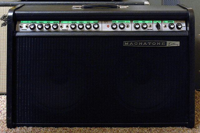
Magnatone MP-3 Guitar Amplifier Repair
I bought a basket-case Magnatone MP-3 guitar amplifier to restore. All that remained was a partial chassis and a cabinet. There were no tubes, speakers, reverb tank and some of the components had been cut from the chassis. I recovered the cabinet, replaced the grill cloth, repaired the amplifier, and replaced the reverb tank and Jensen speakers some years ago. One of the neat features of this 1966 amplifier was the front panel was rear-lit by electroluminescent panels with a dimmer control! The panels and dimmer control were gone so I had no idea what they looked like or how they were installed. I kept searching surplus sites and years later found some electroluminescent panels that were about the right length. Each panel was made up of three sections so I bought three (two to use and one for a spare). The panel was the perfect length for the right side but too short for the left side. I cut my extra panel off after the first section and used this to extend the left side. These panels are powered from the secondary high voltage side of the transformer through a series limiting resistor and rheostat to control the brightness. The legends looks pretty slick! This picture was taken with normal overhead lighting and the dimmer control on the lowest setting.

Marantz 2240 Legend Restoration
I have a Marantz 2240 receiver which the power legend had worn off. I made a new legend using decal paper and Schneidler Mediaeval Black fonts. I scaled the fonts to 70% height to compress them and added a bit of horizontal spacing between the letters. I tried a reverse image and gluing the transfer directly to the front but I never could find a glue that I could wipe away the excess without destroying the legend edges. Instead I made a regular decal with 3 coats of lacquer as a binder and used a soft tip brush with lacquer thinner to blend the edges of the binder. The legend is a bit lower in contrast with a bit too much horizontal spacing. Now that I know how these decals work I could improve the legend but I think it looks good enough.
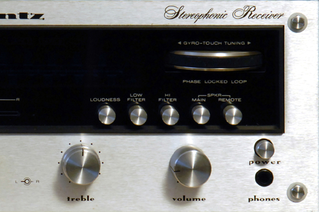
Here is a 3" decal I made and put on a piece of finished birch.
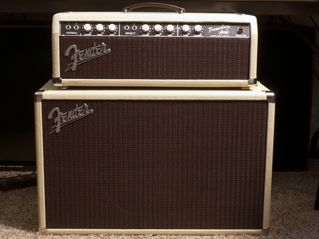
Fender Tremolux Tolex Restoration
I recently restored a 1961 Fender Tremolux. It came out so nice I made a page with more pictures on it here.
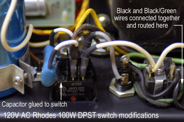
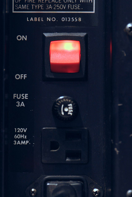
Rhodes 100W Suitcase Repair
I have several Rhodes 73 key suitcase pianos but the newest one has the 100W amplifier and needed the power switch replaced. The neon light no longer worked and I could hear popping and hissing when turned on so I knew it was internally arcing. I believe the original switch was a Carling LTGMO500-TB-B-R/125N and none of the Carling distributors had this in stock. Most all of the other brands of illuminated rocker switches are made for a different size panel cutout. The Philmore 30-16867 red illuminated rocker switch does fits the 1.0 x 1.125 inch panel cutout. The switch has 0.25 inch spade connectors instead of solder lugs and the light is wired to the two center contacts. The Carling switch has the light connected to two isolated contacts so the circuit requires some wiring modifications.
|
120V AC Switch Modification Notes: Caution - this modification deals with primary high voltage wiring. On no account should this modification be attempted if you are not familiar with safe connection of high voltage primary wiring and insulation. Warning - this modification is for 120V AC primary only. 240V AC requires a different modification.
|
Ensoniq EPS-16Plus Fan Modification
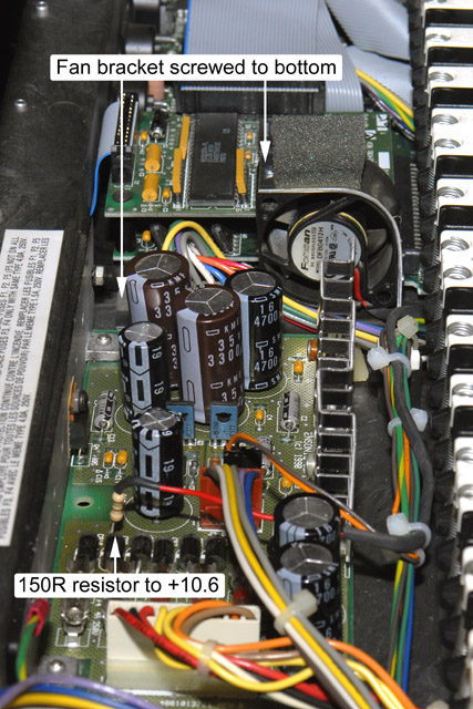
I have two Ensoniq EPS-16 Plus keyboards identical in configuration. One has worked reliably all these years but the second overheats and resets. I had an external fan on the heat sink and decided to install a small +12 volt internal fan. I chose to run the fan off the +10.6 volt unregulated supply that feeds the 7805 regulators as I didn't want to add any more heat to the regulators. There are two small holes between the power supply and the memory/SCSI expander that do not go through the enclosure base. I drilled the one closest to the rear panel through and made a bracket to mount with a 6-32 screw from the bottom. I made the bracket so there would be ~0.25" space between the base and the bottom of the fan for the power supply wires to lay as they are very tight in this area. I added foam under the bracket and a piece on top to press against the front panel PCB to keep the fan from vibrating. The fan runs on ~5.5 volts so it is quiet and exhausts towards the two PCB mounted heat sinks to stir the internal air.
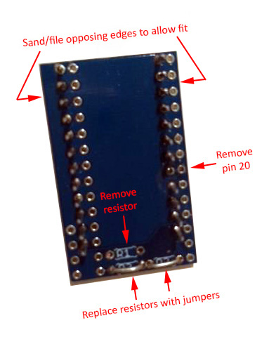
Keytronic Capacitive Keyboard Repair
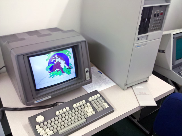
In 1982 I worked on the Unicorn / 4100 program which introduced a family of three low cost color graphics terminals: 4105, 4107 and 4109. I was restoring a 4107/4170 system for or the vintageTEK museum. I was delighted the day I got some graphics programs to run and watched as the screen of the 4107 came to life drawing color vector graphic images. As I ran various programs the keyboard got more difficult to type on as keys would stop working reliably. Eventually, nearly all the keys stopped working.
I was familiar with this keyboard and knew that the problem was deterioration of the foam pads. This keyboard was a Keytronic capacitive keyboard which used aluminized mylar on foam pads which would press down against the keyboard when a key was depressed. After 29 years the foam had simply rotted. Each key press simply compressed the foam more and more until the aluminized mylar would no longer make contact with the PCB. I searched on the web and found an article on repairing a Processor Technology SOL-20 which used a similar keyboard (I was also amused because the first computer I built in 1976 emulated a SOL-20).
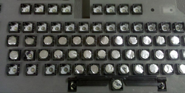
You can flip the original foam sandwich (aluminized mylar-foam pad-plastic pad) out with a small screwdriver hooked under the plastic pad (be careful as sometimes they really shoot out of there and can be easily lost). The foam wipes off the back of the aluminized mylar but I found I needed to use lighter fluid to clean the residue off the plastic pad.
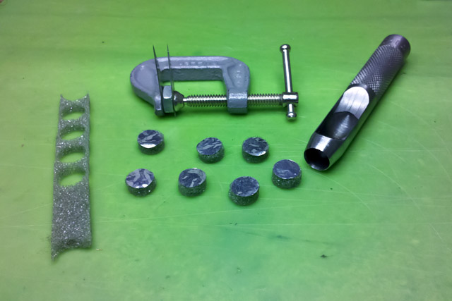
I was apprehensive that parallel knife blades would really cut the foam but it worked quite well. I used two #11 X-Acto blades held with a C clamp on each side of a 0.20" thick nut. The knife blades are not very long so you can't cut through thick foam. I used 0.5" foam which worked fine. I used a standard 7/16" hole punch to cut the foam although I found I needed to sharpen it considerably to cut clean edges. I cut the foam on a smooth board using a slight twisting motion. I glued the clear plastic pad onto the foam and then glued the foam on to the aluminized mylar. The only issue I found was that application of contact cement on the aluminized mylar caused it to curl up so I held it flat with a pick while applying the cement and then would press the foam onto it while sliding the pick out.
After making a few pads I found this process worked best. If you make a mistake or want to redo a pad, a small amount of acetone into the foam will wick and loosen the contact cement.
|
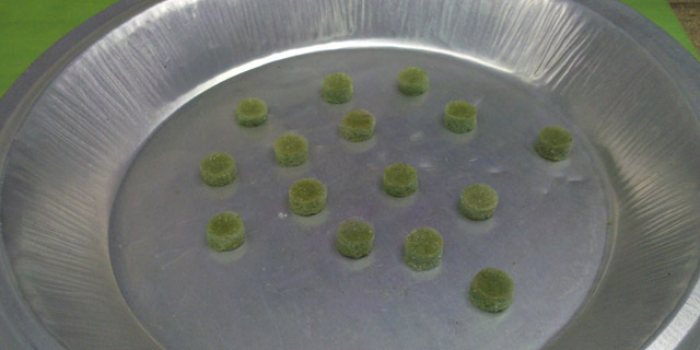
I let the pads dry a full 24 hours before inserting them into the keyswitches. The pads aren't quite perfectly flat, but they will flatten when depressed. Some of them seemed a bit short so I increased the thickness to 0.215" which seemed to work fine.
|
And the good news is the keyboard was fully functional! Here is the 4107 color graphic terminal displaying images from the 4170 local graphics processing unit.
We've also done a 4115 capacitance keyboard repair at the vintageTEK museum and have a video on our Repair Videos page.
Dallas DS1287 Dead Battery Repair
I restored a Tektronix 2402A GPIB controller for or the vintageTEK museum. The BIOS uses a Dallas DS1287 RTC which has an internal battery that was dead. The BIOS defaults are not correct for operation and upon exiting the BIOS the system reboots, so it checks and determines that the battery is dead and again loads the defaults. I found an excellent repair page for the Dallas DS1287. I found it easiest to cut into the sides of the module with an X-Acto knife and then scrape down to the pins with a small screwdriver. You can use the X-Acto knife to cut under the ground pin to separate the battery and solder new wires onto the pins. I used a 3V coin cell that I mounted on top of a pair of unused ROM sockets.
Mostek MKB36000 Read Only Memory Repairs
We had a couple of early 1980's oscilloscopes at the vintageTEK museum which used the Mostek MKB36000 ROMs which are known to deteriorate over time (e.g. FROMs - Forgetful Read Only Memories). One was a Tektronix 468 Digital Storage Oscilloscope which used a pair of the ROMs. There was room to retrofit an adapter board to convert the 24 pin ROM socket to a 28 pin EPROM socket and I copied the binary contents of a pair of good ROMs to a pair of 2764 EPROMs. I made my adapter boards but later found these inexpensive ones at http://store.go4retro.com/2364-adapter/. An adapter board is a bit wider and longer than the standard 24 pin outline but there is ample room in the 468. Contact me if you need the binary contents.
The Tektronix 7854 Oscilloscope with Digital Storage proved more of a challenge. There are two pairs of ROMs stacked very close together so there was insufficient room for four adapter boards and the board to board spacing and the PCB ejectors limited the vertical height. I could fit a two adapters at U200 and U210 so I had to copy a good set of ROMs and combine them into a pair of larger 27128 EPROMs. I had to solder individual pins to minimize the height (e.g. not a strip of pins) and use a low profile socket for the EPROM although it really should be soldered directly to the adapter. I had to fly a wire for A14 to the 27128 and combine the two chip select signals into one. Unfortunately the oscilloscope would not operate without the patch EPROMs and FPLA which we did not have but I did find the binary files which include the FPLA patch here. This eliminates the need for the FPLA! Programming up a pair of 27128s and a pair of 2716 patch EPROMs brought this oscilloscope back to life. Programming and PCB modifications are documented here updated.
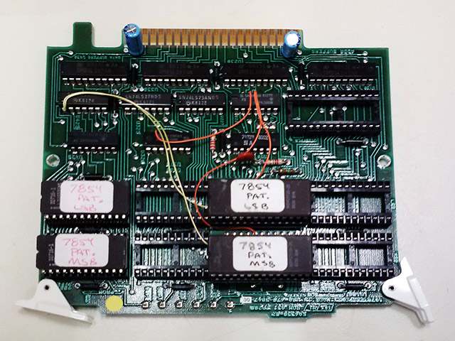
Note my labels do NOT match my documentation. I know what I meant!
The patch eproms are on the left and the code eproms are to their right.
I did find commercially available adapters, either PCB-only or assembled. Make sure they match this schematic. An individual sent me his experience using the Retro Innovations adapter. It required a few modifications, including making the adapter a bit narrower so the two would fit side by side.
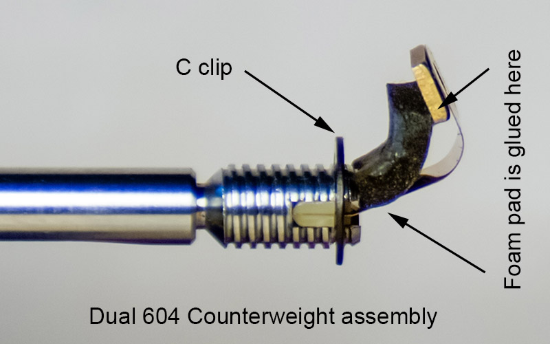
Dual 604 Counterweight Repair
I repaired a Dual 604 turntable and one of the issues was the counterweight flops down quite loose. The counterweight is mounted on a flat spring to not be rigid on the tonearm but it should be parallel with the tonearm and centered in the adjustment shell. Inside the assembly the flat spring is in an "L" shape which attaches the counterweight to the shaft. At a diagonal of the "L" is attached a foam pad "spring" in tension to keep the flat spring in shape. This pad was stuck onto the spring with adhesive backing that has since deteriorated. I removed the pad, cleaned all traces of adhesive, and reglued it with contact cement. After assembly, there is a small inset setscrew which can fine tune the angle such that the counterweight will be parallel to the tonearm shaft and centered in the adjustment shell.
Kustom Reverb Repair
I bought a 1970 Kustom K-150-2 head that the reverb did not operate. The reverb input transducer was open and I was able to remove and repair it. I drilled the head off of the brass rivet that holds the transducer laminations and remove the coil and laminations. The open was right at the pin so I was able to unwind a turn and re-wrap the wire around the pin and solder it. I soldered the rivet to the backing plate so it wouldn't turn and tapped it with a 4-40 thread so I could reassemble it with a brass screw.
![]()
The reverb hold-down mechanism was complete except it was missing the collet that compresses to hold the plunger in. I simply machined one out of aluminum and it works great. This is the reverb hold-down plunger.
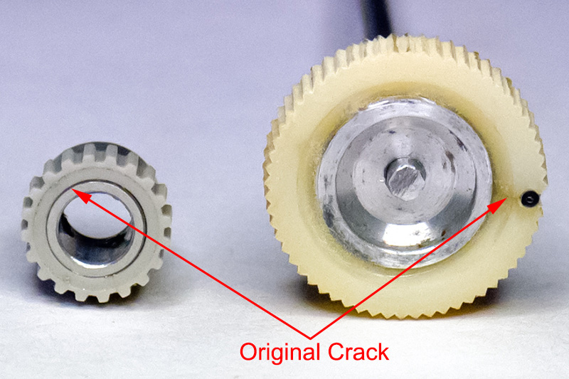
Plastic Gear and Knob Shrinkage Repair
I do repairs on vintage Tektronix equipment at the vintageTEK museum. There are a number of plastic knobs and gears that were press fit or molded over aluminum hubs. The plastic continues to shrink and eventually cracks. The pen turret drive gear in a Tektronix 4662 plotter and the thumb wheel on a Tektronix W plugin are two such examples. The plastic is intact but no longer fits around the hub. I simply turned down the diameter of the hub on a lathe to fit the smaller diameter of the plastic surround and glued it back on with epoxy. It worked quite well.
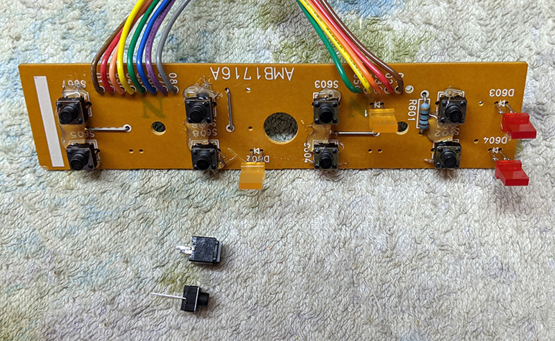
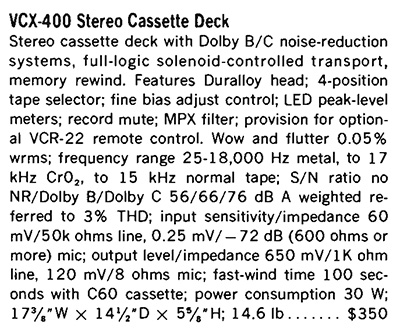
Vector Research VXC-400 Repair
I bought this cassette deck new in 1983 for $269. This review is from the 1984 HiFi Stereo Review Tape Recording Guide.
The only switch that would function was the Pause button. The switches are small rubber dome with carbon disks and all the normally used ones had increased in resistance to the point the BA843 tape deck controller IC would no longer recognize them. These switches were 6mm x 6mm and 7mm in height with only two pins. I found some Bojack 6*6*6 tactile switches that had the same footprint but were shorter. I mounted them temporarily on the PCB and assembled the switch mechanism with the pushbuttons. I then reflowed the pad and adjusted the switches so they were just touching the back of the pushbuttons. I then added hot glue around the perimeter to hold the switch in place as they were now about 1.2mm off the PCB. They worked great. You can see the height difference between the original switch and the replacement below it.