|
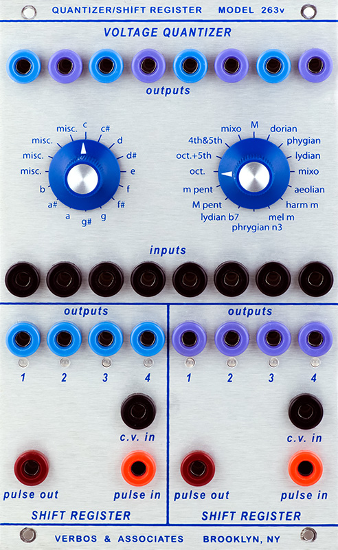
Verbos &
Associates |
|
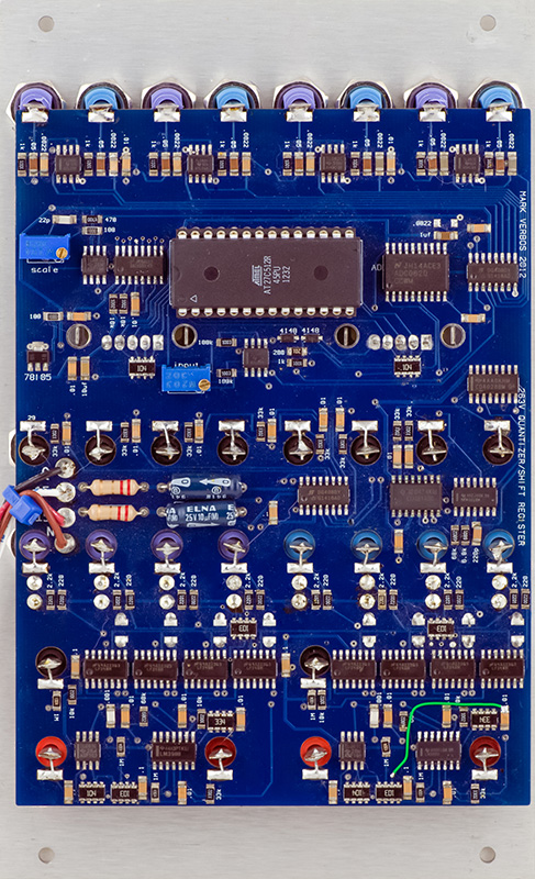
I was sent a a 263V for repairs. The quantizer required calibration and one of the shift registers was faulty.
The module is mostly SMT with a few thru-hole components.
There are just two calibrations for the quantizer. One trimmer sets the scale of the output voltages and the unlabeled trimmer sets the threshold. Calibration is straightforward. Set the controls to "C" and Octave. Apply a CV to the input and adjust it until the corresponding output increases. Adjust the scale value so the increment from the 0V input to the increment is exactly one octave. In this case, I was adjusting for 1.2V/Oct and at 0V the output was 25 mV. I adjusted the output for the first increment to 1.225V and checked as I increased the CV for octave steps at 2.425V, 3.625V, etc.
Next adjust the CV to the octave threshold, in this case 1.2V, and adjust the unmarked trimmer so the output increments at 1.200V input. Check that the output voltage increments at 2.400V, 3.600V, etc.
The ASR fault was interesting. The sampling clock to the LF398 was actually inverted so it tracked with a very small hold time. I found a via that had become intermittent and bypassed it with the green wire.
Operation
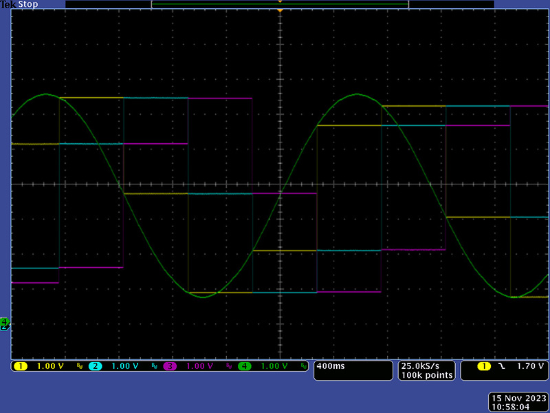
Here are some scope images of the ASR in operation. Since I only have a 4 channel oscilloscope I had to use three separate photos. This photo shows the input CV (green) and outputs 1, 2, and 3 (yellow, cyan, and magenta). Where the green trace touches the yellow trace is where a sampling pulse occurs. You can see output 1 sample to the input CV. On the next clock, you can see the cyan sample to the previous value of the yellow, and on the next clock you can see the magenta sample to the previous value of the cyan.
In this scope image you can see the green sample pulses. The same sequence of events occurs. There is a slight delay from the rising edge of the sample clock to the sampled value. There is an internal narrow clock generated from the rising edge and this delay is due to the generation of that clock.
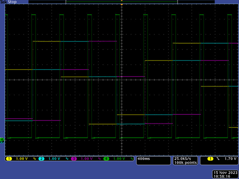
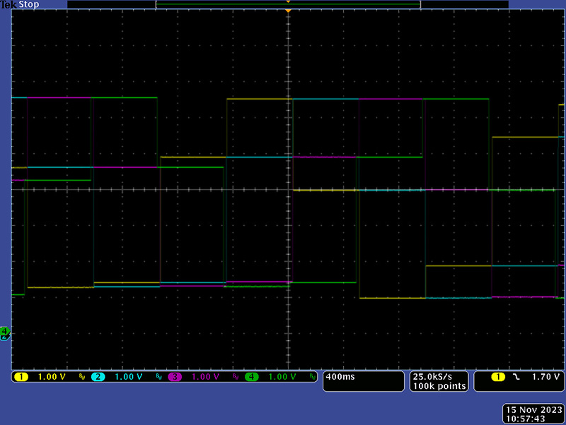
Finally, this scope image shows all four channels where you can see the sampled CV transfer from yellow to cyan to magenta to green. The two ASRs can be serialized to form an 8 channel ASR.