 |
Aries
AR-328 |
|
Aries modules were available both as kits and factory modules. This module did not appear in the 1975 catalog and sold in 1977 for $159.00 in kit or $235.00 assembled. This module appear to be a kit due to the build and solder quality.
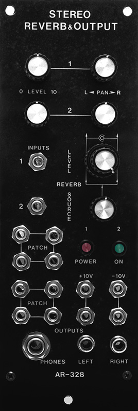
The topology of this module is a bit odd. It has two inputs which can be panned to either the right or left output. Independent level controls adjust the amount of dry signal to each output. There are two spring reverbs with level controls that adjust the wet signal to each output. However, the two spring reverbs are fed from the same mono signal which can be panned between the two inputs. I would have thought that each spring reverb would have independent drive for true stereo reverb. There are also some patch jacks and +/-10V jacks as well as a main power switch and indicator for the synthesizer. The module originally had a 4 pin Cinch-Jones plug for the power switch and indicator lamp. The owner didn't need these so I replaced them with Lumix LEDs to indicate +/-15 volts.
I combined specifications and schematics from Robert Leiner (with permission) and my photos into a PDF document.
AR-328 Spring Reverb and Output Document
The module originally had four RCA shielded cables for the reverb tanks. I replaced them with panel mounted RCA jacks so stereo patch cords could be used to connect the reverb tanks. The additional shielded cable and jacks can be seen in this photo.
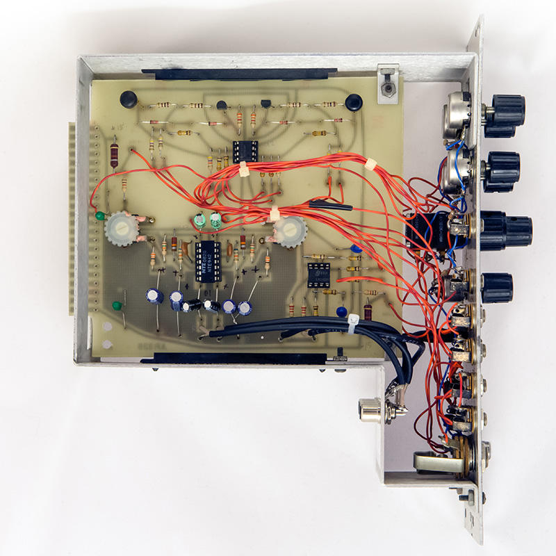
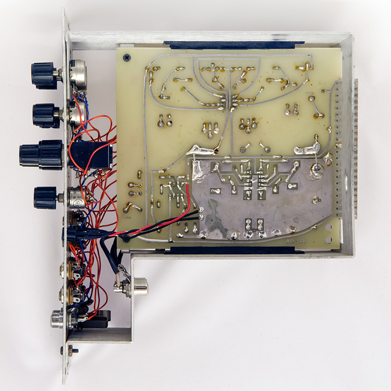
The four RCA jacks are mounted on the lower rear chassis so there is plenty of room for patch cables.

The PCB is a single sided tin with no solder mask. Care is required when doing repairs as the pads do lift easily. The layout depends on the trimmers connecting the grounds so I added two jumpers on the rear of the PCB. You can see the additional wiring for the LEDs in this photo.
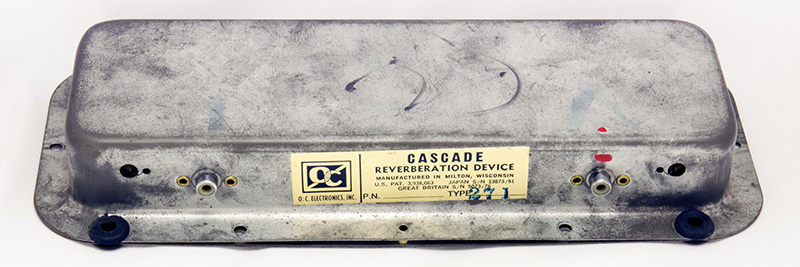
The reverb tanks are identical Type 271 made by O. C. Electronics. There is little information available on O. C. Electronics or these reverb tanks. O. C. Electronics was formed by Gibbs employees to compete against Accutronics reverb tanks. These are folded line reverbs where the input and output transducers are not in line and a solid wire connects the two reverb springs forming the letter "Z". Many of the O. C. Electronics folded line reverb tank stickers state "Made By Beautiful Woman In Milton Wisconsin Under Controlled Atmospheric Conditions."

Modifications
There are two adjustments to set the bias point of the LM381 dual preamp to Vcc/2. This module had been repaired previously and the LM381 replaced with an NTE942. The DC level of both outputs was nearly at +15 volts and the reverb signal was severely distorted.
The LM381 is used in a single ended configuration so the impedance of the feedback point is about 10K. For bias stability the feedback resistor impedance needs to be about 1/5 or about 2K. The feedback circuit consists of R46 (R51) and R47 (R52). R47 (R52) should be (Vbe/(5 x Ifb)) or 1K3 which is about in the center of the trimmer range. R46 (R51) should be (((Vcc/1.3)-1) x 1K3) or about 13K7, not 47K.
I changed R46 (R51) from 47K to 15K and I could easily adjust the DC output level to 7.5 volts. The AC gain of the circuit depends on the ratio of R46 (R51) and R45 (R50) so I changed R45 (R50) from 120R to 33R to increase the gain slightly from 390 to 450. I have no idea how this circuit worked with the original resistor values but it required these modifications for a clean reverb signal. Now it sounds quite good!