|
Arduino ComputerVoltageSource Module |
|
I program AVRs in assembly code but thought it might be time to play around with the Arduino development environment. I chose the Arduino Mega2650 and wrote a couple of programs using the PWM output to generate CVs. The challenge is using the base Arduino is the tradeoff between minimizing the PWM ripple with a low pass filter and having responsive step response. I found the PWM outputs adequate for slow moving CVs such as a triangle wave LFO but quite inadequate for something like a quantizer. In addition the 5V output range is divided into 255 steps for 20 mV increments which is 6% off of an 83 mV semitone.
I decided to look for DAC shields and was surprised to not find any high quality as most shields were PWM based or R2R ladders. I have some extra DAC7714s from my ComputerVoltageSource so decided to interface one of these to the Mega 2650 on a prototype shield. The DAC requires +15V so I planned to use a Murata MEE1S0515SC small form factor +5 to +15 DC-DC converter along with my 10.666V reference voltage for accurate semitones.
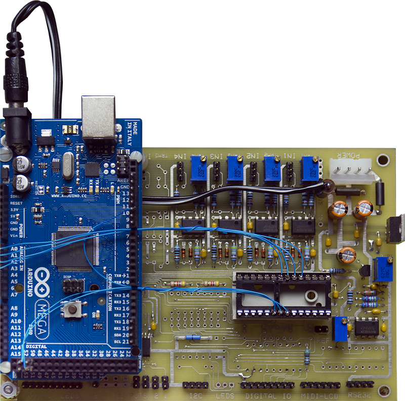
Then it dawned on me that it would be easier to replace the AtomPro processor on my CVS with the Arduino Mega 2650. I only need to wire up the 4 analog inputs and the 3 SPI lines for a basic 4 channel version (no I2C, start, stop, and aux) I had an extra four channel CVS board for my CVS Kurzweil ribbon controller project so I used it. Here is a photo of the Arduino Mega 2560 wired to my CVS board.
DAC Timing
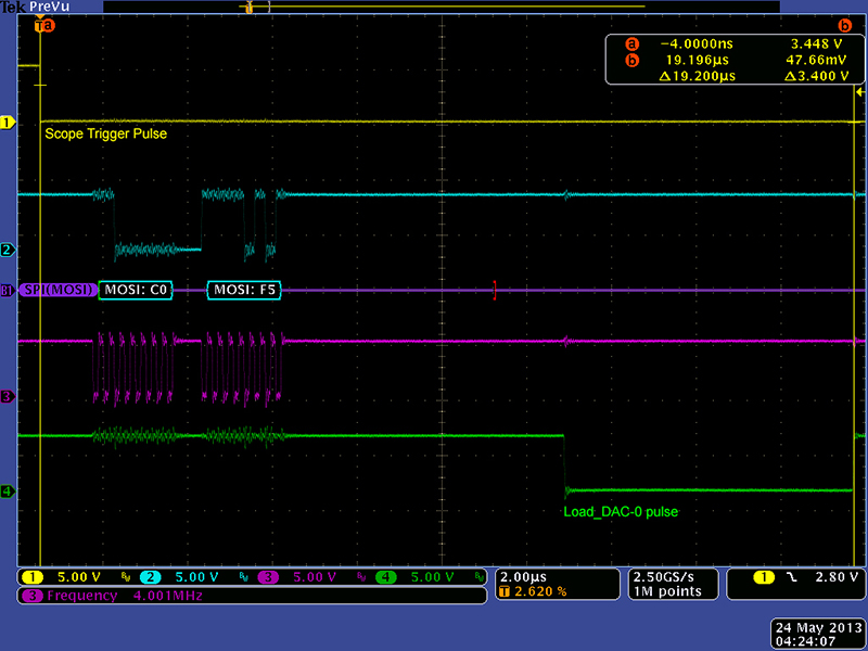
The Arduino does not support 16 bit SPI transfers so you have to concatenate two 8 bit transfers. There is no pulse output command so you have to toggle a pin for the Load_DAC pulse which surprisingly takes about 7 uS. The Arduino is about 6X faster for loading all four DACs but this is somewhat expected since the AtomPro uses a software SPI library and the Arduino uses the native AVR hardware SPI support. Increasing the SPI clock to 8 MHz resulted in a negligible time difference since the Load_DAC pulse becomes the dominant time. Here you can see the SPI timing for loading one DAC with the standard 4 MHz clock.
Arduino Load_DACs SPI test code
I mounted the Arudino on top of the CVS and wired up the 4 analog inputs and the 3 outputs to interface to the DAC. This 4 channel Arduino-based CVS does not yet have the Start, Stop or Aux inputs nor the I2C lines wired up. I added a 56R 1W resistor between +15V and the Arduino power in to drop half of the 10V.
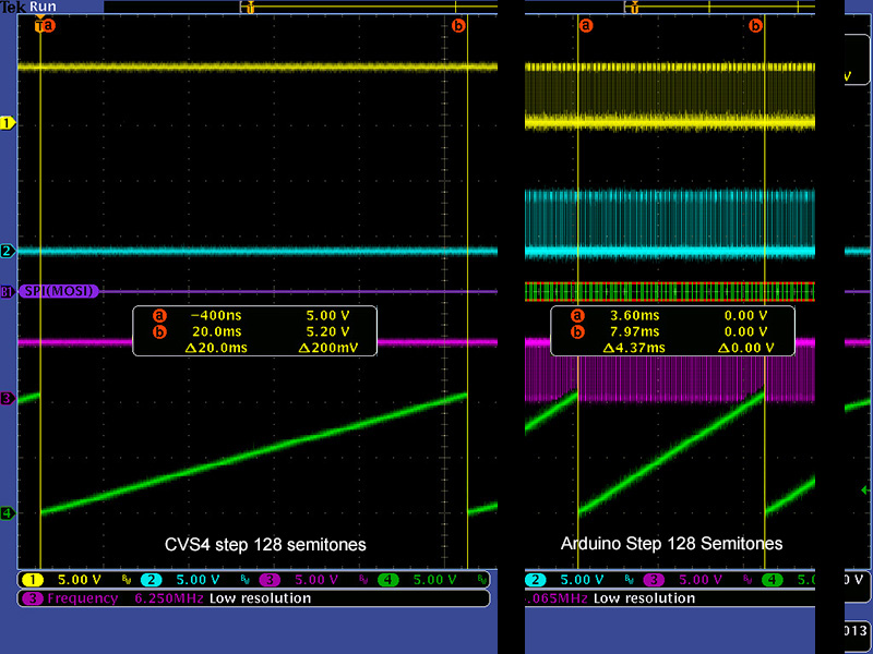
I wrote a quick program to output all 128 semitones (0 to 10.624V) to a single DAC running on the Arduino which took 4.37 mS to execute (right). Similar optimized code for a single DAC running on the CVS4 (no I2C DAC switching overhead) took 20 mS to execute (left). The Arduino drops to about 4.5X faster execution in a program dominated by DAC output but not really enough to open up new application possibilities. Certainly LFO programs could could run to higher frequencies. Few people were willing to tackle BASIC programming so I think only a tiny few would ever write in C. Certainly it makes an interesting development environment and the Arduino has sufficient pins that I could use parallel DACs which would drop the overhead even more. Maybe someday ...